

Home > Electrical & Electronics > Electrical Control System > ALSTOM MBCI01N1AB0761B Auxiliary Variable Speed Relay
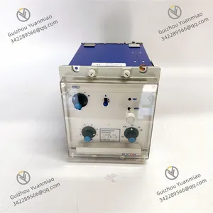
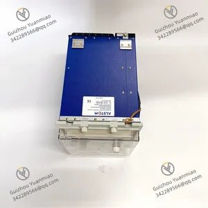
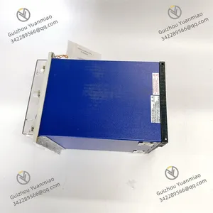
ALSTOM MBCI01N1AB0761B Auxiliary Variable Speed Relay


Negotiable
MOQ: 1 Piece (Price negotiable depending on order volume and customization)
Key Specifications
Get Latest Price
Material:
Other, Global universal model
Condition:
Other, Global universal model
Task:
Other, Global universal model
Payment & Shipping
Payment Methods:
Port of Shipment:
China
Delivery Detail:
Delivery time depends on order quantity.
Related Products
-
 ALSTOM MCGG22D1CB0753C Programmable Logic ControllerNegotiableMOQ: 1 Piece
 -
ALSTOM MCGG22L1CB0753E Programmable Logic ControllerNegotiableMOQ: 1 Piece
-
ALSTOM MCGG52H1CB0753C High-Performance Control ModuleNegotiableMOQ: 1 Piece
-
ALSTOM MCGG62N1CB0753F High-Performance Control ModuleNegotiableMOQ: 1 Piece
-
ALSTOM MCHN02D1AB0004A Bus Expansion ModuleNegotiableMOQ: 1 Piece
Material
Other, Global universal model
Condition
Other, Global universal model
Task
Other, Global universal model
Mathematical Model
Other, Global universal model
Signal
Other, Global universal model
Customized
Non-Customized
Structure
Other, Global universal model
Analog output range
4-20mA
Number of channels
4
Working voltage
38V
FeaturesWorking Principle
Electrical Wiring
Mechanical Fixing
If panel installation is adopted, use matching screws to fix the module on the control cabinet panel, ensuring firm installation to prevent wiring looseness due to vibration.
Power-on Initialization
Basic Function Testing
Functional Parameter Configuration
Load Linkage Test
Operation Monitoring and Optimization

Send Inquiry to This Supplier


Business Type
Trading Company
Year Established
2014
Factory Size
1,000-3,000 square meters
Product Certifications
SA8000
You May Also Like
-
ALSTOM MCHN02D1AB0005A Control ModuleNegotiableMOQ: 1 Piece
-
ALSTOM MCTI40N1AB0751G Trapezoidal Logic Control Communication Interface ModuleNegotiableMOQ: 1 Piece
-
ALSTOM MFAC14K1AA0001A CPU ModuleNegotiableMOQ: 1 Piece
-
ALSTOM MFAC34N1AA0001A Control ModuleNegotiableMOQ: 1 Piece
-
ALSTOM MVAA14B1AA0785C Low-Voltage RelayNegotiableMOQ: 1 Piece
-
ALSTOM MVAJ13D1GB0780A Digital Line Protection RelayNegotiableMOQ: 1 Piece
-
ALSTOM MVAJ21L1GB0771B Control ModuleNegotiableMOQ: 1 Piece
-
ALSTOM MVAJ23B1AB0757B Current RelayNegotiableMOQ: 1 Piece
-
ALSTOM MVAJ27L1FB0784D Digital Protective RelayNegotiableMOQ: 1 Piece
-
ALSTOM MVAJ53H1LB0856A Low-Voltage RelayNegotiableMOQ: 1 Piece


