Home > Electrical & Electronics > Electrical Control System > ALSTOM MVAJ13D1GB0780A Digital Line Protection Relay

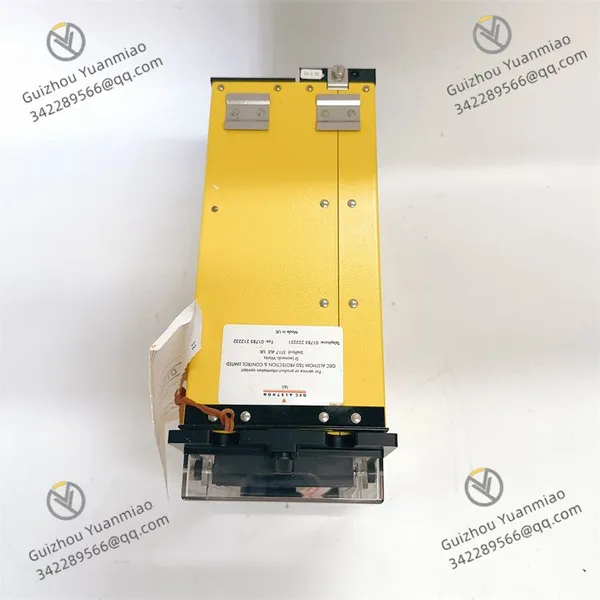
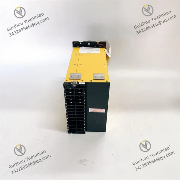
ALSTOM MVAJ13D1GB0780A Digital Line Protection Relay
ALSTOM MVAJ13D1GB0780A Digital Line Protection Relay photo-1
ALSTOM MVAJ13D1GB0780A Digital Line Protection Relay photo-2
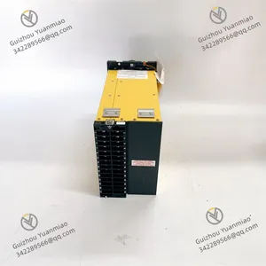
ALSTOM MVAJ13D1GB0780A Digital Line Protection Relay photo-3
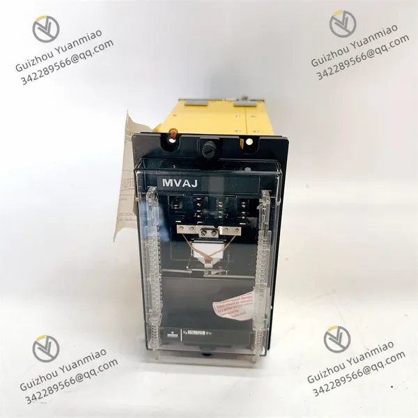
Negotiable MOQ: 1 Piece (Price negotiable depending on order volume and customization)
Key Specifications
Get Latest Price
Material:
Other, Global universal model
Condition:
Other, Global universal model
Task:
Other, Global universal model

Payment & Shipping
Payment Methods:
Port of Shipment:
China
Delivery Detail:
Delivery time depends on order quantity.
Material Other, Global universal model
Condition Other, Global universal model
Task Other, Global universal model
Mathematical Model Other, Global universal model
Signal Other, Global universal model
Customized Non-Customized
Structure Other, Global universal model
Input voltage 90-300Vac
Output voltage 21-29Vdc
Output current range 0-86A
Power 1800W
Efficiency ≥92%
Operating temperature -40℃ to +55℃
MTBF 400,000 hours
ALSTOM MVAJ13D1GB0780AFunctional Features
  • Comprehensive Protection Functions: Equipped with overcurrent protection, overvoltage protection, undervoltage protection, frequency protection, thermal protection, and ground fault protection. Capable of full-range monitoring and safeguarding of power systems, providing precise and rapid response to abnormal conditions to prevent damage to electrical equipment.

  • Advanced Communication Capabilities: Supports multiple communication protocols (e.g., Modbus RTU/TCP), enabling seamless integration with various control systems via interfaces such as RS485 and Ethernet for remote monitoring and management.

  • Wide Operating Range: Input voltage range: 90-250V AC; Output voltage: 24V DC; Rated current: 2A. Operates reliably in temperatures from -20°C to +70°C, suitable for harsh industrial environments.

  • High-Efficiency Technology: Utilizes advanced high-frequency pulse width modulation (PWM) edge resonance technology for optimal efficiency.

  • Precision Performance: Features high voltage regulation accuracy, fast dynamic response, low output noise, strong anti-interference capability, and wide temperature tolerance.

  • Intuitive Display: Real-time voltage and current monitoring via digital LCD or Chinese character display panel.

  • Integrated Protection Circuitry: Built-in equalization/float charge switching circuit with manual/auto control options.

  • Monitoring Interface: Enables remote status monitoring, power control, charge mode switching, and is equipped with automatic current sharing bus, equalization charge bus, and system battery current limiting interfaces.

MVAJ13D1GB0780A (3)

Working PrincipleCore Structure & Components
As an ALSTOM power protection and control device, its operation is based on a closed-loop system integrating power parameter monitoringlogic processing, and protection execution. Key components include:
  1. Detection Unit: Embedded current/voltage sensors for real-time acquisition of electrical parameters (e.g., current, voltage, frequency).

  2. Control Unit: Integrated programmable logic controller (PLC) or dedicated microprocessor for signal processing and logical decision-making.

  3. Execution Unit: Relay contacts or solid-state switches for circuit interruption based on control unit commands.

  4. Communication Module: Supports industrial protocols (e.g., Modbus, PROFINET) for data exchange with host systems or other devices.

Operational Flow
  1. Parameter Acquisition & Signal Conversion:
  • The detection unit converts high-voltage/current primary signals into low-level analog signals (e.g., 0-5V, 4-20mA) via electromagnetic induction or Hall effect principles.

  • Analog signals are digitized by an analog-to-digital converter (ADC) and transmitted to the control unit.

  • Logic Processing & Protection Decision:
    • The control unit analyzes digital signals against preset thresholds (e.g., overload current, undervoltage limits) and logic programs.

    • Triggers protection logic when parameters exceed thresholds (e.g., 1.2x rated current) or abnormal conditions (e.g., voltage sag) are detected.

  • Protection Execution & Action Output:
    • Control unit commands the execution unit to actuate relay contacts (e.g., disconnect main circuit) or sends alarm signals via communication interfaces.

    • Some models support time-delayed protection (e.g., inverse-time characteristics) to avoid false trips by adjusting response time based on fault severity.

  • Communication & Remote Monitoring:
    • The communication module packages device status data (e.g., operating parameters, fault codes) into standard protocol frames (e.g., Modbus RTU) for upload to monitoring systems.

    • Operators can remotely configure protection parameters, query historical fault records, or manually control device actions via host computers.

    MVAJ13D1GB0780A (1)

    Implementation Logic of Typical Protection Functions
    • Overload Protection: Calculates action time based on overload multiple (following inverse-time characteristics) when current exceeds the rated value, then disconnects the circuit upon reaching the threshold.

    • Short Circuit Protection: Instantly triggers rapid tripping when a sudden current surge exceeds the short-circuit threshold, preventing equipment damage.

    • Undervoltage/Overvoltage Protection: Monitors voltage deviations (e.g., 120% of rated value) and executes power-off protection after a delay to prevent motor burnout or insulation damage.

    System Integration & Coordination Mechanism
    Typically functioning as a terminal protection node in power systems, this device collaborates with superior monitoring systems (e.g., SCADA) or other protection devices (e.g., transformer relays) via communication networks:


    • Receives parameter configuration commands from higher-level systems to dynamically adjust protection thresholds.

    • Uploads fault data for system-wide fault localization and historical analysis.

    • Implements selective protection by prioritizing circuit disconnection closest to the fault location, minimizing outage scope.

    Simplified Working Principle Diagram
    plaintext
    External Power System (Current/Voltage Signals) → Detection Unit (Sensors) → ADC Conversion → Control Unit (Logic Processing)                                                                                      ↓                                                                                  Yes → Execution Unit (Relay Action)                                                                  Is Fault Detected?                                                                                  No → Continue Monitoring                                                                                      ↓                                                                                  Communication Module → Host Monitoring System

    MVAJ13D1GB0780A (2)

    Common Faults & SolutionsPower Supply Faults
    • Symptoms: Relay fails to operate; power indicator light is off.

    • Possible Causes:

      • Input voltage outside 90-250V AC range.

      • Loose or damaged power connections (open circuit, short circuit, or poor contact).

      • Internal power module failure.

    • Solutions:

      • Measure input voltage with a multimeter; check upstream power equipment if abnormal.

      • Inspect/replace damaged power cables; ensure secure connections.

      • If external power and wiring are normal, contact technical support for internal module replacement.

    Communication Faults
    • Symptoms: Communication with host or other devices interrupted; communication indicator abnormal.

    • Possible Causes:

      • Incorrect communication parameters (e.g., baud rate, data bits, parity mismatch).

      • Damaged communication interface (e.g., due to electrostatic discharge, overvoltage).

      • Faulty communication lines (e.g., Open circuit, short circuit, or electromagnetic interference).

    • Solutions:

      • Verify communication settings match other devices.

      • Inspect/replace damaged communication interface modules.

      • Repair/replace communication cables, add shielding to reduce interference, and ensure proper grounding.

    Protection Function Malfunctions (False Trips or No Response)
    • Symptoms: Protection functions activate unexpectedly during normal operation or fail to respond during actual faults.

    • Possible Causes:

      • Improperly configured protection parameters (e.g., incorrect overcurrent/overvoltage thresholds).

      • Faulty measurement components (e.g., current/voltage transformers) leading to inaccurate data.

      • Internal logic circuit failures.

    • Solutions:

      • Reconfigure protection parameters based on actual system operating conditions.
      • Test/replace faulty measurement components (e.g., current/voltage transformers).
      • Contact technical support for internal circuit diagnostics if measurement components are functioning normally.
    Product Tags: MVAJ13D1GB0780A

    Send Inquiry to This Supplier

    * Message
    0/5000

    Want the best price? Post an RFQ now!
    Verified Business License
    Business Type
    Trading Company
    Year Established
    2014
    Factory Size
    1,000-3,000 square meters
    Product Certifications
    SA8000