Home > Electrical & Electronics > Electrical Control System > ALSTOM MCGG22D1CB0753C Programmable Logic Controller

ALSTOM MCGG22D1CB0753C Programmable Logic Controller
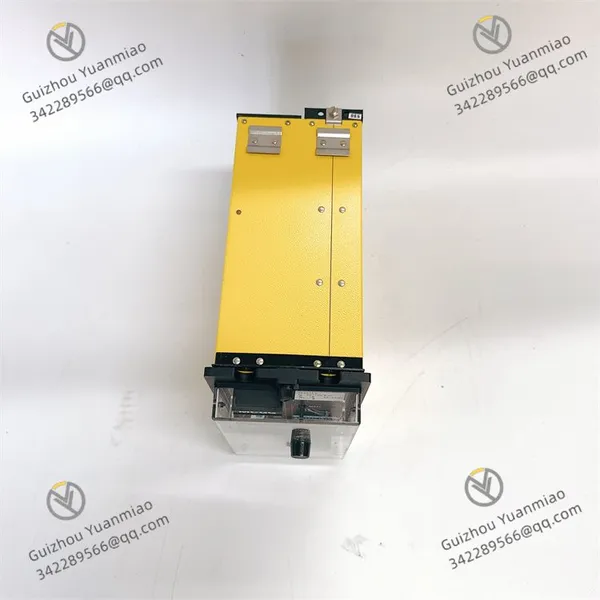
ALSTOM MCGG22D1CB0753C Programmable Logic Controller photo-1
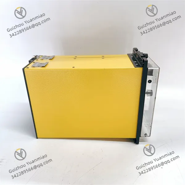
ALSTOM MCGG22D1CB0753C Programmable Logic Controller photo-2
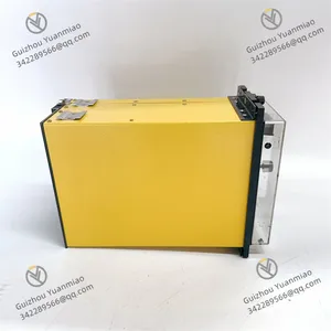
ALSTOM MCGG22D1CB0753C Programmable Logic Controller photo-3
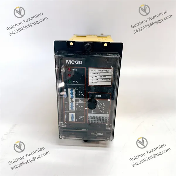
Negotiable MOQ: 1 Piece (Price negotiable depending on order volume and customization)
Key Specifications
Get Latest Price
Material:
Other, Global universal model
Condition:
Other, Global universal model
Task:
Other, Global universal model

Payment & Shipping
Payment Methods:
Port of Shipment:
China
Delivery Detail:
Delivery time depends on order quantity.
Material Other, Global universal model
Condition Other, Global universal model
Task Other, Global universal model
Mathematical Model Other, Global universal model
Signal Other, Global universal model
Customized Non-Customized
Structure Other, Global universal model
ALSTOM MCGG22D1CB0753C
Features
  • Multi-channel Design
    As a 4-channel relay module, it can process multiple signal channels simultaneously, enabling control and monitoring of multiple devices or loops, thus improving system integration and control efficiency.

  • Strong Signal Processing Capability
    Capable of receiving and processing both analog and digital signals, it adapts to different types of input signals and meets the requirements of various industrial control scenarios.

  • Alarm Function
    Supports alarm input and can be connected to external alarm devices or systems for timely response to alarms and dangerous conditions, enhancing system safety and reliability.

  • High Reliability
    Designed and manufactured in compliance with relevant industrial standards, it is suitable for harsh industrial environments, operating stably under conditions such as high humidity and vibration, ensuring long-term stable system operation.

Technical Parameters
  • Operating Voltage
    Typically a standard voltage, but specific values need to be determined according to product specifications. Multiple voltage levels may be available to adapt to different power supply systems.

  • Output Frequency
    Meets the requirements for signal output frequency in industrial control and can be configured and adjusted according to actual applications.

  • Channel Parameters
    Each channel supports specific ranges of analog input/output, such as 4–20mA current output or 0–10V voltage output. Digital input/output complies with corresponding logic level standards.

MCGG22D1CB0753C (3)

Working Principle
  • Signal Input
    Receives analog signals (such as current, voltage) or digital signals (such as switching signals) from sensors, controllers, or other devices, and transmits them to the module's internal processing unit.

  • Signal Processing
    The internal microprocessor or logic circuit analyzes, converts, and processes the input signals. Based on preset programs and algorithms, it determines whether the signals exceed the normal range or meet alarm conditions, etc.

  • Control Output
    According to the signal processing results, it outputs control signals to external devices, such as controlling the opening/closing of relays to achieve control over actuators like motors and valves, or outputting alarm signals to external alarm devices.

  • Communication Function
    If the module is equipped with communication interfaces (such as RS-485, Profibus, etc.), it can communicate with DCS, PLC, or other upper-level systems to realize functions such as remote monitoring, parameter setting, and data transmission.

MCGG22D1CB0753C (1)

Installation Steps
  • Installation Environment Check
    Ensure that the ambient temperature and humidity at the installation location are within the module's allowable operating range, free from strong electromagnetic interference and corrosive gases, and with good ventilation.

  • Rail Installation
    If installing on a standard DIN rail, snap the module into the rail and secure it with rail clips or screws to ensure firm installation and prevent looseness due to vibration or collision.

  • Electrical Connection

    • Connect the power supply circuit according to the module's wiring diagram, ensuring the power voltage matches the module's required operating voltage and paying attention to correct polarity.

    • Connect input signal lines, accurately inserting signals from sensors or other devices into the corresponding input terminals.

    • Connect output signal lines, linking the module's output terminals to the input terminals of controlled devices (such as relays, contactors, indicator lights, etc.).

    • Connect communication lines (if the module supports communication), linking the communication cable to the corresponding interface terminals, and ensuring communication parameters (such as baud rate, protocol, address, etc.) match the upper-level system settings.

  • Grounding Treatment
    Reliably ground the module's grounding terminal to prevent electromagnetic interference and ensure personal safety.

MCGG22D1CB0753C (2)

Debugging Steps
  • Pre-power-on Inspection
    Use a multimeter to check the resistance between power input terminals to ensure no short circuit. Verify that all wiring is secure, terminal screws are tightened, and cables are free from damage or poor contact.

  • Power-on Test
    Switch on the power and observe whether the module's power indicator light is normally on. If the light is off, check the power circuit and module for damage.
    Check the communication between the module and the upper-level system via software or handheld programmers. Send simple commands (such as reading status information or version number) to verify correct response reception.

  • Input Signal Test
    Input different types and amplitudes of analog or digital signals to the module's input terminals, and check whether the module correctly receives and identifies the signals via upper-level software or the module's display function. For example, input a 4–20mA analog current signal and verify that the displayed value corresponds to the input with an error within the allowable range.

  • Output Signal Test
    Send control commands via upper-level software or a programmer to make the module output different control signals, and check the normality of output signals. For modules controlling relay outputs, verify that relay opening/closing actions match the commands; for analog output modules, use a multimeter to measure the voltage or current at the output terminals to ensure consistency with set values.

  • Function Test
    Test various module functions, such as the alarm function. Simulate alarm conditions to check whether the module promptly outputs alarm signals and triggers alarm prompts via the upper-level system or other devices. If the module has multiple channels, test each channel individually to ensure normal functionality.

  • Parameter Setting and Optimization
    Set module parameters (such as input signal range, filtering parameters, output signal type and range, alarm thresholds, etc.) via upper-level software or the module's local interface according to actual application needs. After setting, conduct actual operation tests, observe the module's performance under real working conditions, and further optimize parameters as needed to achieve optimal control effects and performance.

Product Tags: MCGG22D1CB0753C

Send Inquiry to This Supplier

* Message
0/5000

Want the best price? Post an RFQ now!
Verified Business License
Business Type
Trading Company
Year Established
2014
Factory Size
1,000-3,000 square meters
Product Certifications
SA8000