

Home > Electrical & Electronics > Electrical Control System > NI SCXI-1141 Elliptical Lowpass Filter Input Module
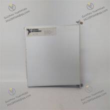
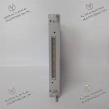
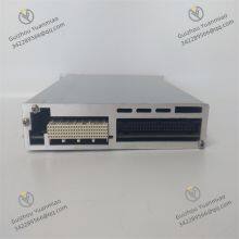
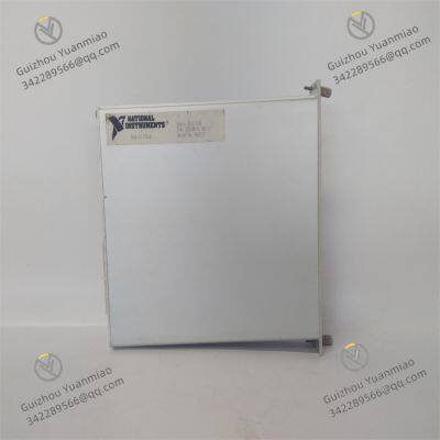
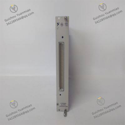
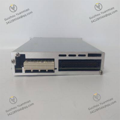
NI SCXI-1141 Elliptical Lowpass Filter Input Module
Negotiable
MOQ: 1 Piece (Price negotiable depending on order volume and customization)
Key Specifications
Get Latest Price
Material:
Other, Global universal model
Condition:
Other, Global universal model
Task:
Other, Global universal model
Payment & Shipping
Payment Methods:
Port of Shipment:
China
Delivery Detail:
Delivery time depends on order quantity.
Related Products
-
 NI SCXI-1160 General-Purpose Relay Switch ModuleNegotiableMOQ: 1 Piece
 -
NI SCXI-1162 Digital I/O ModuleNegotiableMOQ: 1 Piece
-
NI SCXI-1193 32-Channel RF Multiplexer Switch ModuleNegotiableMOQ: 1 Piece
-
NI SCXI-1300 Terminal BlockNegotiableMOQ: 1 Piece
-
NI SCXI-1303 Terminal BlockNegotiableMOQ: 1 Piece
Material
Other, Global universal model
Condition
Other, Global universal model
Task
Other, Global universal model
Mathematical Model
Other, Global universal model
Signal
Other, Global universal model
Customized
Non-Customized
Structure
Other, Global universal model
Stopband Attenuation
120dB
Overvoltage Protection
±30V
Dimensions
1.2×6.8×8.0 inches
NI SCXI-1141Product Features

Send Inquiry to This Supplier

* Email
Want the best price?
Post an RFQ now!

1Yr
Business Type
Trading Company
Year Established
2014
Factory Size
1,000-3,000 square meters
Product Certifications
SA8000
You May Also Like
-
NI SCXI-1324 Terminal BlockNegotiableMOQ: 1 Piece
-
NI SCXI-1325 Terminal BlockNegotiableMOQ: 1 Piece
-
NI SCXI-1326 High-Voltage Terminal BlockNegotiableMOQ: 1 Piece
-
NI SCXI-1600 16-Bit Data Acquisition ModuleNegotiableMOQ: 1 Piece
-
NI PCI-4462 4-Input Sound and Vibration DeviceNegotiableMOQ: 1 Piece
-
NI PCI-5421 High-Performance Arbitrary Waveform GeneratorNegotiableMOQ: 1 Piece
-
NI PCI-6110 Multi-Functional Data Acquisition CardNegotiableMOQ: 1 Piece
-
NI PCI-6221 High-Performance Multifunctional Data Acquisition CardNegotiableMOQ: 1 Piece
-
NI PCI-6229 Multifunctional Data Acquisition CardNegotiableMOQ: 1 Piece
-
NI PCI-6230 Multifunctional Data Acquisition CardNegotiableMOQ: 1 Piece


