








 Contact Platform Support
 Help Center
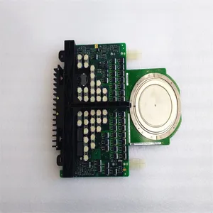
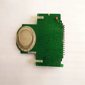
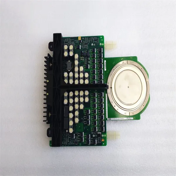
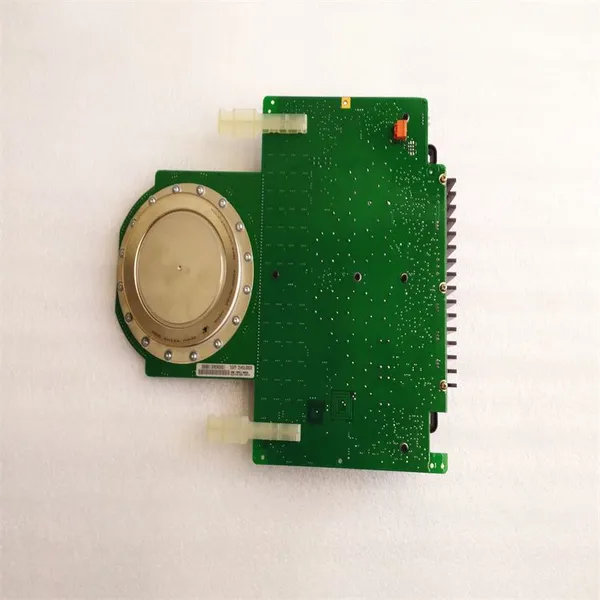
ABB 5SHY3545L0009 3BHB013085R0001 IGCT Module



Related Products
-
 PFSK152 3BSE018877R2 Signal Processor ModuleUS$ 350 - 2100MOQ: 1 Unit
 -
PM864AK01 3BSE018161R1 Processor UnitUS$ 2600 - 7540MOQ: 1 Unit
-
PM866K01 3BSE050198R1 Processor UnitUS$ 2560 - 7840MOQ: 1 Unit
-
PM860K01 3BSE018100R1 Processor Unit KitUS$ 1390 - 4600MOQ: 1 Unit
-
5SHY3545L0014 3BHE023784R0001 IGCT Thyristor ModuleUS$ 2600 - 5100MOQ: 1 Unit
The ABB 5SHY3545L0009 3BHB013085R0001 is an IGCT (Integrated Gate-Commutated Thyristor) module.
The product number is 3BHB013085R0001 The ABB model designation is 5SHY3545L0009, IGCT module. The country of origin is Switzerland, the customs tariff number is 85413000, and the net weight of the product is 3.4 kg.
Application Scenarios: Specifically designed for advanced industrial control systems, it is suitable for scenarios that require efficient power management, such as process automation and power automation. It can ensure the stable operation of the system in harsh environments in high-power applications.
Product Features: Using high-quality materials and advanced manufacturing processes, it has excellent reliability and durability. It can withstand harsh conditions and reduce maintenance requirements. Its compact and lightweight design is convenient for integration, saving space and installation time for renovation or new installation projects. In addition, this module has an advanced design and can be seamlessly integrated into existing industrial control systems, improving system performance without affecting safety standards. It also provides comprehensive technical support and warranty services.
General installation steps for ABB 5SHY3545L0009 3BHB013085R0001 (IGCT, Integrated Gate-Commutated Thyristor): Preparation before Installation Confirm the Equipment and Accessories: Carefully check whether the 5SHY3545L0009 module and all its accessories are complete and intact, including the module itself, cooling device (if any), connection cables, fixing screws, etc. At the same time, verify whether the model and specifications of the module are consistent with the actual application requirements. Read Relevant Documents: Thoroughly read the installation manual, technical specification sheet, safety guidelines and other documents provided by ABB for this module, and fully understand the performance characteristics, installation requirements, precautions, and safety operation procedures of the module. Prepare Installation Tools: Get ready the tools required for installation, such as appropriate screwdrivers, wrenches, torque wrenches (used to precisely control the tightening torque of screws), multimeters (used to check electrical connections), etc. Determine the Installation Environment: Ensure that the installation location meets the environmental requirements of the module. Generally, it is required to be installed in an indoor environment that is dry, well-ventilated, dust-free, free of corrosive gases, and free from strong electromagnetic interference. At the same time, ensure that there is sufficient space for the installation, debugging, and maintenance of the module, and the mechanical strength of the installation location can bear the weight of the module. Safety Protection: Before the installation operation, the relevant power supply must be disconnected, and necessary safety protection measures, such as wearing insulated gloves and safety goggles, should be taken to prevent electric shock and other accidental injuries.
Installation Steps Install the Cooling Device (if any): For the IGCT module, effective cooling is crucial. First, install the cooling device (such as a heat sink, cooling water pipeline, etc.) in the designated position to ensure that the cooling device is firmly installed and well-sealed to ensure the cooling effect. According to the installation instructions of the cooling device, connect the coolant pipeline (if it is liquid cooling) or install the cooling fan (if it is air cooling), and carry out necessary leak detection or ventilation tests. Fix the Module: Carefully place the 5SHY3545L0009 module in the installation position, and use appropriate fixing screws to fix the module on the installation bracket or base. When tightening the screws, operate according to the specified torque and sequence to ensure that the module is firmly installed and evenly stressed, and avoid damage to the module or performance degradation due to improper installation. Usually, a torque wrench is required to precisely control the tightening torque. Electrical Connection: Main Circuit Connection: According to the electrical schematic diagram of the module and the actual application requirements, use cables of appropriate specifications to connect the main circuit terminals (anode, cathode, etc.) of the module to other parts of the system. When connecting, ensure that the cross-sectional area of the cable is large enough to carry the current when the module is operating, and ensure that the connection is firm and the contact is good. You can use terminal blocks or crimping tools for cable connection, and check whether there are any looseness or oxidation at the connection parts. Control Circuit Connection: Connect the control signal cables of the module to the corresponding control interfaces. These control signals may include trigger signals, monitoring signals, etc. Ensure that the cables are connected correctly to avoid wrong connections or short circuits. At the same time, pay attention to the correct grounding of the shielding layer of the cable to reduce the impact of electromagnetic interference on the control signals. Grounding Connection: Reliably connect the grounding terminal of the module to the grounding device of the system to ensure electrical safety. The grounding resistance should meet the relevant standards and requirements. Generally, it is required that the grounding resistance be as small as possible to ensure that the current can be quickly introduced into the ground in case of a fault. Inspection and Testing: After the installation is completed, carefully check all the connection parts to ensure that the screws are tightened, the cables are correctly connected, and there is no looseness or damage. Use tools such as a multimeter to check the electrical connections, measure the resistance values between each terminal, and confirm whether they meet the technical specification requirements. After confirming that all installations and connections are correct, a preliminary power-on test can be carried out (on the premise of ensuring safety) to check whether the module can work normally, and observe whether there are any abnormal heating, smoking, or other abnormal phenomena. If any problems are found, the power supply should be disconnected immediately, and troubleshooting and repair should be carried out.

Send Inquiry to This Supplier


You May Also Like
-
5SHX1445H0001 3BHL000391P0101 IGCT ModuleUS$ 1680 - 3570MOQ: 1 Unit
-
PFTL101A-2.0kN 3BSE004172R1 Pillow Block Type Load CellUS$ 2360 - 4850MOQ: 1 Unit
-
PFCL201C-20kN 3BSE027070R20 Pressductor PillowBlock Load CellsUS$ 2560 - 4800MOQ: 1 Unit
-
PPD113B01-10-150000 3BHR023784R1023 Excitation ControllerUS$ 1680 - 4650MOQ: 1 Unit
-
5SHY3545L0010 3BHB013088R0001 IGCT ModuleUS$ 2300 - 4800MOQ: 1 Unit
-
S-113H 3BHB018008R0003 RackUS$ 4500 - 10500MOQ: 1 Unit
-
S-093H 3BHB009885R0004 Integrated Gate Converter ThyristorUS$ 2400 - 11000MOQ: 1 Unit
-
S-073N 3BHB009884R5211 Phase ModuleUS$ 2300 - 11500MOQ: 1 Unit
-
S-073N 3BHB009884R0021 High Voltage Frequency ConverterUS$ 2400 - 11600MOQ: 1 Unit
-
S-123H 3BHB030479R0512 Phase High Voltage Inverter ModuleUS$ 2200 - 11800MOQ: 1 Unit


