








 Contact Platform Support
 Help Center
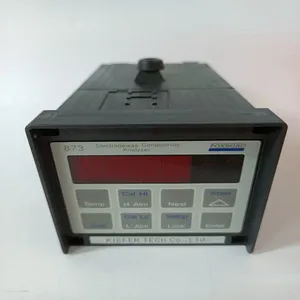
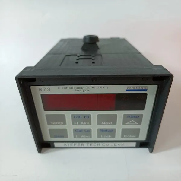
873EC-JIPFGZ


Related Products
-
 SY-1025115C SY-1025120E 0399143 SY-0301060RUS$ 1120 - 2130MOQ: 1 Piece
 -
SY-1025115C SY-1025120E 0399144 SY-0301059FUS$ 1121 - 2131MOQ: 1 Piece
-
SY-60702001RA SY-61025006RA SY-61025004RAUS$ 1121 - 2131MOQ: 1 Piece
-
FCP270 P0917YZUS$ 1122 - 2132MOQ: 1 Piece
-
A4H124-24FX P0973JNUS$ 1159 - 2059MOQ: 1 Piece
Brand: FOXBORO
Type:873EC-JIPFGZ
Origin: the United States
Warranty: 365 days
Colour: new/used
Shipping method: Courier delivery
Use the following procedure to install the processor units along the DIN-rail: 1. Mount the processor units. 2. Mount the communication interfaces on the CEX-Bus to the left of the processor unit. If BC810s are used, the configuration of the segments should be considered. If no BC810s are used, the interfaces can be divided between the two CPUs in any preferred way. 3. Press the units gently together and make sure that the CEX-Bus is correctly connected, via the connectors on the baseplates. 4. If BC810s are used, connect the TK851 cable to the two BC810s (Figure 31 on page 100). If no BC810s are used, mount the CEX-Bus extension cable TK850 to the units at farthest away from the processor units or, if no units are mounted, directly to the CEX-Bus on the processor unit. The CEX-Bus extension cable must be connected to both CPUs whether or not there are any other CEX-Bus units (Figure 29 on page 93).
Connect the RCU Link Cable TK851 to both CPUs. Note that in redundant CPU configuration, COM3 and the electrical ModuleBus on the baseplate can not be used. 6. Baseplates cable connections: a. Connect the power leads to both CPUs and the power supervision signals from SS8xx to screw terminals SA and SB (see Figure 28 on page 83). b. Connect the Control Network cables to CN1 (single bus connection) or CN1 + CN2 (redundant bus connection). The Control Network is connected to both CPUs. c. Connect the Control Builder to COM4 with cable TK212 of the Primary CPU (if required for changing an IP address etc.). Otherwise connect the Control Builder to the Control Network. 7. Connect the optical ModuleBus to the optical contacts on the processor units (see Figure 2 on page 32 and Figure 40 on page 131). Information regarding optical cable selection and cable length is provided in the S800 I/O documentation. Note that the RCU Link Cable TK851 must be used and can not be replaced by a similar cable. Using another cable will disable the identification of the CPUs in the CB and Operator Station. When running in single configuration the RCU Link Cable TK851 might temporarily be used to perform the function of a termination plug. The CPU connected to the RCU Link Cable connector marked “UPPER” will be defined as “UPPER” in the Control Builder and Operator Station. The marking has no relevance to the physical placement of the CPUs. Any CPU can become the Primary CPU. Both CPUs should be powered from the same supply (single or redundant). For redundant power supply, see Figure 46 on page 140. Connection to the optical ModuleBus is identical to that for the processor unit and for the FCI in S800 I/O (Figure 55 on page 161).

Send Inquiry to This Supplier


You May Also Like
-
A2H124-24FX P0973BJUS$ 1160 - 2060MOQ: 1 Piece
-
FBM207C RH917GYUS$ 1167 - 2067MOQ: 1 Piece
-
FBM219 RH916RHUS$ 1167 - 2067MOQ: 1 Piece
-
FBM237 RH914XSUS$ 1168 - 2068MOQ: 1 Piece
-
RH924YFUS$ 1168 - 2068MOQ: 1 Piece
-
FBM227 P0927ACUS$ 1206 - 2215MOQ: 1 Piece
-
SSA-T8028-0652US$ 1214 - 2223MOQ: 1 Piece
-
FBM233 P0926GXUS$ 1035 - 2255MOQ: 1 Piece
-
A4H254-8F8TUS$ 1068 - 2059MOQ: 1 Piece
-
FBM230 P0926GUUS$ 1076 - 2067MOQ: 1 Piece


