

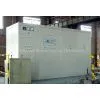
MF Induction Furnace


Negotiable
MOQ: 1 Set (Price negotiable depending on order volume and customization)
Key Specifications
Get Latest Price
Brand Name:
XMMT
Place of Origin:
China
Model Number:
Payment & Shipping
Payment Methods:
Port of Shipment:
China
Delivery Detail:
7 days
Related Products
-
 MF Induction Furnace Melting SystemNegotiableMOQ: 1 Set
 -
MF Induction Furnace Melting SystemNegotiableMOQ: 1 Set
-
Efficient Copper Cable Granulator for Scrap Wire RecyclingNegotiableMOQ: 1 Set
-
40T Electric Tilting Machine for Heavy Parts RotationNegotiableMOQ: 1 Set
-
Noise-reducing Metal Shredder Low-noise Metal Scrap Shredding Machinery for FactoriesNegotiableMOQ: 1 Set
Brand Name
XMMT
Place of Origin
China
1. Mainly used in foundry workshop
2. Unit Furnace capacity from 500kg to 50 MT.
3. MF power supply from 200Kw to 8000Kw.
4. High efficiency.
5. saving energy.
6. High quality.
7. Best reliability.
2. Unit Furnace capacity from 500kg to 50 MT.
3. MF power supply from 200Kw to 8000Kw.
4. High efficiency.
5. saving energy.
6. High quality.
7. Best reliability.
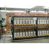
1. Basic working principle
AC current with 50Hz shall be firstly converted into DC current through three phases bridge type rectifier configured with SCR and then, through the inverter, the AC current with medium frequency (shorted as MF below) to be output. The MF power supply then shall, through copper bus-bar and water-cooled electrical cable, feeds power to the inductor (induction coil) of the MF furnace for transforming it into alternating magnetic field, which shall make the metal in the crucible producing eddy current for heating and melting.
2. Equipment features
2.1 On electricity
The solid state power supply (shorted as SPS below) configured with the single integrated circuit Micro-CPU control board, which as the core component for SPS, may detect, display, feedback, follow up control and over-bound protect the electrical parameters such as electric current, voltage, power and frequency, etc., also detect and protect the parameters of water cooling such as water temperature and water pressure, etc.
2.2 Perfect protective measures
It includes: detect/protection for network over-voltage, under-voltage and phase absence of network, detect/protection for cooling water in higher temperature, lower water pressure and less flow rate and detect for SPS in self network over-voltage and over-current, etc., which to be referred in detail on the .
2.3 Easy operation
For operation, it is easy to follow. All the electricity and voltage control, frequency tracking, etc. shall be automatically done with the controlling system. And so, for normal operation, only by switching on the main power with starting SPS, inching power control button, the best power value for melting and holding may be got right away.
2.4 Digital control
The control panel taking as the core the Micro-CPU is adopted for the control system of the SPS, with digital control realized for rectifier and inverter, which is higher in automatic extent and accuracy than analog control system.
2.5 Graphic display
With LCD graphic display equipped at the interface for graphic display, it shall display the parameters of working frequency and power, etc. at the varied locations in rectifier and inverter, as well as the operating states of power supply at real time.
1. Brief introduction on the structure
The furnace consists of the furnace body, pedestal, intake system of water and electricity, furnace lid device, hydraulic system, furnace tilting oil cylinders, swing/lifting cylinders for furnace lid (available for FN more than 1.5t), push out device for worn lining (to be equipped according to the user's demand) and crucible alarming device, etc.
3.1 Furnace body
It mainly consists of induction coil, magnetizer (magnetic shunt), furnace lining, furnace lid and furnace spout, etc.
3.1.1 Inductor (induction coil)
As the core for transition between electricity and magnetism, the inductor is the key component of the induction furnace and it is wound into helix with rectangle copper tube, the inner layer is coated with high strength insulating paint and the exterior layer is wrapped with mica tape. The coil grout with high insulation and heat resistance is coated between turns and on the coil inner surface, which has enhanced insulating and mechanical strength of the coil and has delayed the metal liquid penetrating onto the coil surface, with service life of the inductor prolonged. In addition, several insulation support bars have mounted outside of the turns of the inductor, which are solidly fixed with bolts welded on the turns. And in this way the axial direction of the coil has been ideally positioned and fixed, having increased mechanical strength and avoided coil insulation destroy from friction between the turns and reduced the furnace vibration. At the upper and lower location of the inductor is equipped a water-cooling coil, which aims at evenly heating lining to relieve it from thermal stress for prolonging the service life.
3.1.2 Magnetic shunt
At the exterior along the diameter of the inductor are set up many long magnetic shunts which are laminated with high quality silicon steel sheets, which are used to fix the coils of the inductor with radial to form the solid support, preventing the inductor from emitting magnetic flux outward to avoid furnace shell heating. The magnetic shunts to be water cooling in this project.
3.1.3 Furnace lining
What the so called furnace lining is the furnace hearth sintered with the rammed refractory materials filled between the inductor and the crucible form, which is shaped into straight cylinder form and the metal to be melted inside. The coil grout shall be coated closely along the inner surface of the inductor, with heat insulating material paved on the surface (two layers of ceramic fiber cloth δ=2.5) and after that, refractory material shall be filled and rammed inside. The refractory material shall be sintered into lining of crucible through warm up and heating.
3.1.4 Furnace frame
It is a kind of skeleton structure welded with shape steel and steel plate and in the interior is set up inductor, magnetizer (magnetic shunts) and lining, etc. structuring into an entirety, on the top of which is mounted an operation platform with furnace tap through equipped at the front and at the both side of which are mounted furnace tilting oil cylinders that are connected with cylinder ends to be used as connecting aperture for tilting and turning.
3.1.5 Alarming electrode of crucible At the bottom of the furnace body are designed two apertures, which are mainly used to extend the lead of alarming electrode to the outside of the furnace body. The alarming electrodes of the crucible are classified into two: one is bottom electrode made of stainless steel wire Φ1.0, one end of which is touching metal liquid and the other led out for grounding. Made of stainless wire net with 6mesh, the lateral electrode is laid inside the inductor and at the location 4~6 spot along the circle 300 away from the lower limit stainless wire is led through and tied, extending out of hearth with porcelain bead and connecting with the designed terminal of the alarming device. When the metal liquid leaks into the lining and approaches the lateral electrode, the current on the alarming device shall rise to the designed value (the value to be set in advance), and by this, alarming works. However, this alarming setup is only for reference, because at the beginning of baking furnace or during primary melting, false alarming may occur because of lining too wet. If high temperature metal is to be melted, grounding test bar may be needed so as to go on observing leakage current changing trend after the bottom electrode damaged.

Send Inquiry to This Supplier

Business Type
Trading Company
Total Employees
101 - 200 People
Main Markets
North America, South America, Eastern Europe
Location
Xianyang, Shaanxi, China
You May Also Like
-
Automatic/manual Fluidized Bed Dip Powder Coating Equipment Line for Refrigerator Shelves ProductionUS$ 2000 - 40000MOQ: 1 Set
-
Vertical Scrap Metal Baler With 5.5kW Motor & Safety Lock SystemNegotiableMOQ: 1 Set
-
Automatic Gabion Basket Wire Mesh Forming and Welding MachineNegotiableMOQ: 1 Set
-
Metal Zipper Chemical Cold Plating Machine (13 Tanks)US$ 1,000 - 10,000MOQ: 1 Set
-
Made In China JOY 1330/1325 Portable Air Plasma Cutting MachineUS$ 2,000 - 6,900MOQ: 1 Set
-
Automatic Infrared Length Cutting SystemNegotiableMOQ: 1 Set
-
Factory Supply Stainless Steel Sheet Polishing MachinesUS$ 2,000 - 5,000MOQ: 1 Set
-
Cheap Copper Wire Scrap 99.99 Recycling MachineUS$ 13,000 - 16,999MOQ: 1 Set
-
High Output Recycling Copper Wire Machine/Wire Recycling Machine/Copper Wire Recycling MachineUS$ 2,000 - 15,000MOQ: 1 Set
-
Nails Making Machine India/nail Production Line 0086136736385830NegotiableMOQ: 1 Set


