








 Contact Platform Support
 Help Center
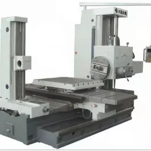
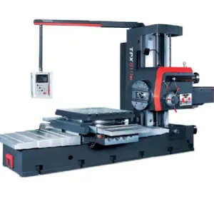
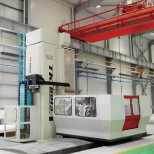
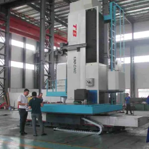
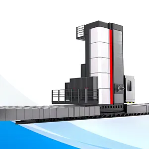
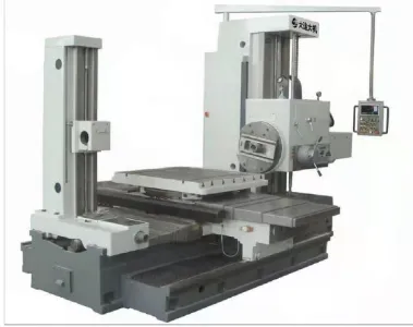
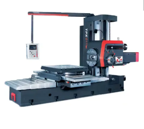
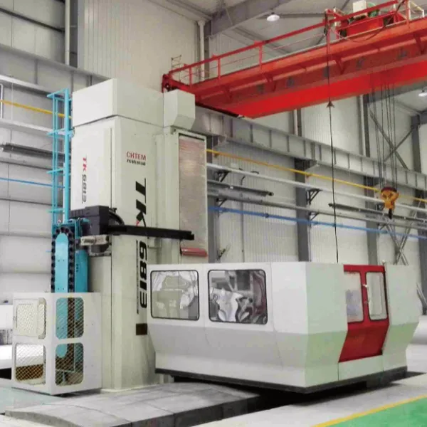
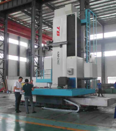
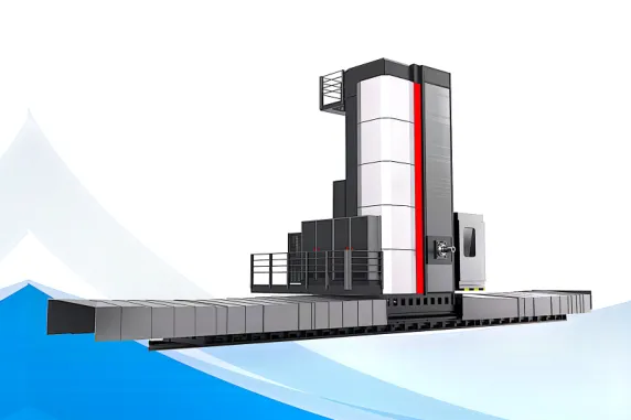
Boring Machine Horizontal Boring and Milling Machine

Related Products
-
 CNC Boring Machine Horizontal Boring and Milling MachineNegotiableMOQ: 1 Unit
 -
Boring Machine Horizontal Boring and Milling MachineNegotiableMOQ: 1 Unit
-
Cnc Vertical Lathe Vertical Turning and Boring MillNegotiableMOQ: 1 Unit
-
Cnc Edm Die Sinker Machine EDM450 EDM540 EDM650 EDM750 EDM850 EDM1260US$ 5500 - 1500000MOQ: 1 Unit
-
Cnc Vertical Lathe VTC600 VTC700 VTC1000NegotiableMOQ: 1 Unit
2.4 Main technical parameters (standard)
Serial Number |
Name and technical requirements |
Units |
Values and notes |
CNC horizontal boring and milling machine | |||
1 |
Boring shaft diameter |
mm |
Phi 130 |
2 |
Milling shaft end diameter |
mm |
Phi is 221.44 |
3 |
Boring shaft cone holes |
ISO 50( JT50 7:24 ) |
|
4 |
Pull-nail model |
D50 DIN69872 |
|
5 |
Main motor power |
Kw |
30 |
6 |
Boring shaft speed |
r/min |
2-2000r/min |
7 |
Countertop size |
mm |
2500 * 2500 |
8 |
Work tables come standard with load bearing |
Kg |
20000 |
9 |
Table move X axis |
mm |
3000 |
10 |
Headstock vertical Y-axis |
mm |
2000 |
11 |
Post longitudinal Z axis |
mm |
1500 |
12 |
Square ram W axis |
mm |
800 |
13 |
Boring shaft axial V shaft |
mm |
seven hundred |
14 |
Table turn B axis |
° |
360 |
15 |
Bench T-slot width |
mm |
28 |
16 |
Minimum distance from spindle end face to worktable center |
mm |
0 (spindle, ram sticking out) |
17 |
Distance from spindle center to work surface |
mm |
100-2100. |
18 |
Square ram section dimensions |
mm |
380 x 420 |
Maximum speed of working feed | |||
19 |
X-axis |
mm/min |
Stepless adjustable, 1-6000mm/min |
20 |
Y and Z axes |
mm/min |
Stepless adjustable, 1-6000mm/min |
21 |
V-axis |
mm/min |
Stepless adjustable, 1-3000mm/min |
22 |
W axis |
mm/min |
Stepless adjustable, 1-3000mm/min |
23 |
B axis |
r/min |
0 ~ 1 |
Move quickly for maximum speed | |||
24 |
X, Y, V axes |
mm/min |
6000 |
25 |
W, V axis |
mm/min |
6000 |
26 |
B axis |
r/min |
1.5 |
3 Main structural features
The overall design layout of the machine tool is vertical and horizontal bed is T-shaped structure, the column is moving vertically, the table is moving horizontally, the spindle box is moving up and down, the table is doing rotary movement, there is a square ram, the spindle can move before and after. The main components are column, bed, slide seat, spindle box head, square ram, table rotating table, table slide seat, table bed composition.
The headstock is a closed structure; Two rectangular guide rails are designed on the column, and reinforcement bars are arranged inside the column to obtain high stiffness and high shock resistance. The column and the slide seat are rigidly connected, and the slide seat and the column are driven to move along the bed by pretightening double nut ball screw pair. The ball screw nut is installed on the slide seat, the ball screw is fixed on the bed, and the servo motor drives the screw to rotate through the precision gear reduction box to drive the column to move.
The machine tool operating box is a suspended centralized operation, which is set on the top of the column. The cantilever is provided with a balanced counterweight, and the operating station can rotate and adjust the height at will. The button station is equipped with a hand-held operation unit, which is convenient to use when setting the knife.
The B-axis table is equipped with the hydraulic brake of the cylinder, and the high-pressure cylinder is applied to the rotating circle in many points to tighten, which improves the stability of the rotating table. Can be positioned at any Angle, the rotary table adopts hydraulic brake tight, can be stopped at any Angle, can realize the Angle processing. The traditional form can only be positioned in the 90 degree direction. The rotary table uses a precision encoder for Angle positioning, which can make the positioning accuracy controlled in 8 arcseconds. The traditional positioning is the positioning block positioning, with the positioning block wear, positioning accuracy is difficult to ensure.
The machine tool can realize six-axis numerical control and any four-axis linkage. The X axis is the movement of the workbench, the Y axis is the vertical movement of the main axle box, the Z axis is the longitudinal movement of the column, the V axis is the movement of the spindle, the W axis is the movement of the ram, and the B axis is the rotation movement of the rotary table.
Machine tool installation: CNC working platform surface can be level with the surface of the working platform, the full stroke of the table linear movement is set up a fully closed protective cover, to prevent foreign bodies from grinding the guide rail, to ensure the internal cleaning of the machine tool, the protective cover is made by a professional factory, beautiful appearance and reasonable structure.
The column, slide seat, bed, workbench and other basic large parts of the machine tool are made of high-quality cast iron, which is aged treatment to eliminate internal stress. The overall rigidity is good, and has good vibration absorption and anti-vibration performance.
3.1 Spindle:
3.1.1 The main shaft of the machine tool is composed of the boring main shaft (boring shaft) and the milling main shaft (milling shaft). The main shaft bearing adopts the imported bearings (FAG) with high speed, good rigidity and high precision. Ensure the spindle rotation accuracy is high, high stiffness, long life, low noise.
3.1.2 In order to prevent the bearing temperature from rising too high when the spindle is rotating at high speed and affecting the spindle accuracy, constant temperature oil cooling is used to reduce the bearing heat output and ensure the working accuracy of the spindle.
3.1.3 The boring shaft is made of 38CrMoAlA high quality alloy steel, which is finished by multiple processes. The surface of the boring shaft is nitrided to ensure sufficient hardness and wear resistance of the boring shaft.
3.1.4 The boring shaft is equipped with a tool clamping device, the use of claw type nail structure, tool tension by the pre-loaded disc spring group to achieve, the loose tool by hydraulic drive, automatic tool clamping safe and reliable.
3.1.5 The main drive system adopts AC spindle motor; The main drive is a three-speed mechanical transmission, so that the main shaft can obtain a stepless speed regulation of 1 ~ --2000 RPM. The main transmission gear is grinding hard tooth surface gear, the main transmission system is in the main shaft box, the transmission rigidity is good, the operation is smooth, the transmission torque is large, and the maintenance is convenient.
3.2 Guide rail:
3.2.1 The X axis, Y axis, Z axis and B axis of the machine tool are constant current hydrostatic guide rails, each static pressure point is easy to adjust, and the movement and operation are stable.
3.2.2 The X axis and Z axis moving guide rail adopts low friction coefficient and plaster-coated sliding guide rail, which has the characteristics of small friction coefficient, small wear, good vibration absorption, high positioning accuracy, self-lubrication, etc.
3.2.3 Y-axis guide rail is a composite sliding guide rail with tin-bronze plate and soft strip attached to guide rail, which has the characteristics of small friction coefficient, wear resistance, good vibration absorption, high positioning accuracy, self-lubrication and so on. It is easy to maintain and can ensure the smooth motion of each moving part.
3.2.4B axis adopts composite guide rail form with wear-resistant guide rail

Send Inquiry to This Supplier



You May Also Like
-
Cnc Gantry Machining Center Gantry Cnc Machining Center Gantry Milling MachineUS$ 120000 - 500000MOQ: 1 Set
-
Gantry Cnc Machining Center Gantry Milling Machine 2015 2518 3015 3020 4020 5032US$ 120000 - 500000MOQ: 1 Set
-
Gantry Cnc Machining Center Made in China 2015 2518 3015 3020 4020 5032US$ 120000 - 500000MOQ: 1 Set
-
Cnc Edm Die Sinker Machine EDM350US$ 5500 - 1500000MOQ: 1 Unit
-
Cnc and ZNC Edm Die Sinker Machine EDM450US$ 5500 - 1500000MOQ: 1 Unit
-
Gantry Cnc Machining Center Made in China 2015 2518 3015 3020 4020 5032US$ 120000 - 500000MOQ: 1 Set
-
DK7732 DK7740 DK7755 DK7765 DK7780 DK77100 Wire Cutting Machine Cnc WedmUS$ 5500 - 1500000MOQ: 1 Unit
-
Sevro Moto Wire Cut Machine Cnc Wedm With Larger TaperUS$ 5500 - 1500000MOQ: 1 Unit
-
Wire Cutting Machine Cnc Wedm With Larger Taper ±30°US$ 5500 - 1500000MOQ: 1 Unit
-
Cnc Edm Die Sinker Machine Electric Discharge Machine Znc Edm Die Sinker MachineUS$ 5500 - 1500000MOQ: 1 Unit


