








 Contact Platform Support
 Help Center
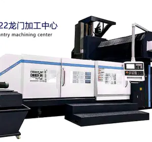
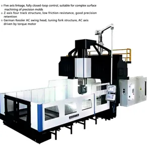
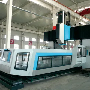
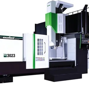
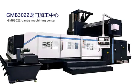
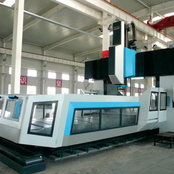
Gantry Cnc Machining Center Made in China 2015 2518 3015 3020 4020 5032

Related Products
-
 Gantry Cnc Machining Center Made in China 2015 2518 3015 3020 4020 5032US$ 120000 - 500000MOQ: 1 Set
 -
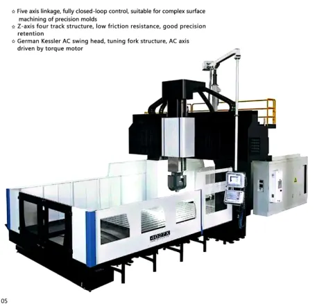
Five Axis Gantry Cnc Machining Center Made in China 2015 2518 3015 3020 4020 5032US$ 120000 - 500000MOQ: 1 Set
-
Turret Milling Machine Milling Machining CentreUS$ 8000 - 100000MOQ: 1 Set
-
VMC(vertical Machining Centre) CNC Milling MachineUS$ 28000 - 100000MOQ: 1 Set
-
Vertical Machining Centre Vmc855 CNC Milling Machine Vmc966 Vmc1165US$ 28000 - 100000MOQ: 1 Set
1.2 The X and Y axes are equipped with heavy-duty roller guideways, offering high rigidity and excellent dynamic accuracy.
1.3 The three-axis drive system uses Taiwan-made large-diameter precision-ground double-nut ball screws, providing a compact structure, smooth motion, and high precision. The screw supports employ precision screw support bearings with pre-tensioning at both ends to eliminate accuracy loss caused by thermal expansion.
1.4 The crossbeam features a stepped design with a large cross-sectional area and wide guide rail span. The short distance from the spindle center to the guide rail surface reduces overturning moment, ensuring superior structural rigidity.
1.5 A high-rigidity Taiwan-made gantry-specific spindle is used, lubricated with grease to ensure consistent and reliable bearing lubrication—economical, environmentally friendly, and enabling long-term maintenance-free operation.
2. High Precision and High Dynamic Response
2.1 The spindle employs high-precision angular contact ball bearings, delivering both high rigidity and exceptional rotational accuracy.
2.2 The XY-axis roller guideways offer high precision, high load capacity, low friction, reduced low-speed crawling, excellent positioning accuracy, and outstanding dynamic response characteristics.
2.3 The Z-axis adopts a hydraulic balancing cylinder structure, which is simple in design and easy to maintain.
2.4 The Z-axis square slide block has a cross-section of 450×450 mm, providing strong rigidity.
3. High Efficiency
The spindle speed can reach up to 3000 rpm, and the maximum rapid traverse speeds for the three axes are 10/10/10 m/min.
4. Wide Processing Range
Compared to machines of similar specifications, this machine’s 5.4 m door width ensures a broader processing range.
5. The gantry slide is designed as a cantilever structure; the longer the cantilever, the weaker the rigidity. In principle, machining should be performed at the top end of the slide to maximize rigidity (as shown in the figure). For customers machining thin-walled parts, it is recommended to use height extension blocks.
6. Z-Axis Thermal Expansion Compensation (optional function) helps address Z-axis thermal elongation during prolonged machining. Customers with high requirements for surface finish quality are advised to add this feature.
IV. Standard System Functions
1. CNC Functions
Minimum resolution: 1 μm
Maximum travel speed: 10/10/10 m/min
Linear, circular, and helical interpolation
Automatic acceleration/deceleration control
Reference point return
Coordinate system setting
MDI function
M, S, T functions
Fixed milling cycles
2. CNC Programming
Programming unit: 0.001 mm, 0.001°
Maximum programmable dimension: 99999.999
Metric/imperial programming
Absolute/relative instruction programming
Macro programming
Subroutine calling
Plane selection
Workpiece coordinate system setup
Local coordinate system setup
Coordinate rotation, scaling, mirroring
3. Editing
Background editing
Character search and replacement
File deletion and copying
4. Display
Chinese menu interface
Graphical display
Status display
Current position display
Program display
Program error display
Operation error display
Alarm display
Axis settings display
Spindle speed
Self-diagnostic function
5. Interpolation Functions
Linear interpolation, up to four axes
Circular interpolation
Helical interpolation
6. Tool Compensation
Tool length compensation
Tool radius compensation
7. Operation
10.4-inch color LCD display
Handheld control unit
8. Operation Modes
Automatic
Single block
MDI
Point operation
Stepper incremental feed
Handwheel incremental feed
Manual/automatic return to reference point
Feed hold
Dry run
9. Feed Axis Functions
Feed rate adjustment: 0% to 150%
Rapid traverse adjustment: 0%, 25%, 50%, 100%
10. Spindle Functions
Spindle speed: controlled via PLC programming
Spindle speed adjustment: 50%–120%
11. Other Functions
Program protection function
V. Installation Requirements
1. Temperature
To maintain machine tool machining accuracy within standard range, the ambient temperature should be kept between 17°C and 25°C, with a daily temperature variation of no more than ±2°C.
If the required precision of machined parts is lower than the machine's factory specifications, the ambient temperature range may be extended to 10°C–38°C.
2. Humidity
Continuous: below 75% (no condensation)
Short-term: below 95% (no condensation)
3. Altitude
Below 1,000 meters
4. Installation Site Conditions
To ensure high precision and optimal performance, the foundation must be constructed strictly according to the foundation drawings provided by the supplier (refer to the foundation drawing for detailed requirements).
The installation site should be away from direct sunlight, vibration sources (such as stamping machines, roads, railways), heat sources (furnaces, heaters, radiators), and electromagnetic interference sources such as high-frequency motors and welding machines, to prevent machine malfunctions or loss of accuracy.
5. Air Source Requirements
Air source pressure ≥ 0.6 MPa; filtration accuracy of 100 μm.
To ensure normal operation, if the compressed air does not meet these requirements, an air purification system (dehumidification, oil removal, filtration) must be installed before the air enters the machine. Moisture in the compressed air can damage precision components such as the spindle and linear encoders (damage caused by this reason is not covered under warranty); strict control is essential.
6. Power Supply
Three-phase 380 V ±10% 50H Z
If the local power supply voltage is unstable, a voltage stabilizer should be installed to ensure normal operation of the machine tool.
7. Power Requirements
Power capacity: 65 kVA
Recommended cable size: 25 mm²
Switch capacity: 160 A
8. Grounding
Proper grounding is required. It is recommended that each machine tool be grounded separately using copper conductors with a cross-sectional area no less than 16 mm², and the grounding resistance should be less than 4 ohms.
VI. Standard Delivery Contents
Portal-type machining center GMF8054R — 1 unit
Including the following configurations and accessories:
| No. | Name | Quantity | Remarks |
|-----|------|----------|---------|
| 1 | CNC system | 1 | |
| 2 | Handheld operation unit | 1 | |
| 3 | Electrical cabinet air conditioner | 1 | |
| 4 | Automatic lubrication system | 1 | |
| 5 | Three-color indicator light | 1 | |
| 6 | Spindle blow-off device | 1 | |
| 7 | Chip removal system | 1 | |
| 8 | Lighting device | 1 | |
| 9 | Random accessories | 1 set | Includes hex key set, Phillips and flathead screwdrivers, etc. |
| 10 | Documentation | 1 set | |
| 10.1 | Packing list | 1 | |
| 10.2 | Certificate of conformity | 1 | |
| 10.3 | User manual (mechanical part) | 1 | |
| 10.4 | User manual (electrical part) | 1 | |
| 10.5 | Electrical operation manual | 1 | |
| 10.6 | CNC system operation manual | 1 | |
| 10.7 | Main purchased components documentation | 1 | |
VII. Main Specifications and Technical Parameters
| Product Model | GMF8054R | Option | Unit |
|---------------|----------|--------|------|
| Worktable | Worktable dimensions | 8000 × 3500 | mm |
| Door width | 5400 | mm |
| Worktable load capacity | 50 | T |
| T-slot width | 17–28 × 200 | mm |
| Machining range | X-axis travel | 8500 | mm |
| Y-axis travel | 6000 | mm |
| Z-axis travel | 1250 | mm |
| Distance from spindle face to worktable | 160–1410 | mm |
| Spindle | Cone type | BT50 |
| Pull-stud specification | P50T-1-MAS403 (45°) |
| Speed range | 10–3000 | rpm |
| Inner diameter of front spindle bearing | φ100 | mm |
| Main drive configuration | Spindle motor + dual-speed gearbox |
| Feed | Cutting feed speed range | 7 | m/min |
| X-axis rapid traverse | 10 | m/min |
| Y-axis rapid traverse | 10 | m/min |
| Z-axis rapid traverse | 10 | m/min |
| System configuration | FANUC OI MF 1 package |
| Motor configuration | X-axis motor | αiF40 with FAN |
9 kW
53 Nm
Y-axis motor αiF30
7 kW
30 Nm
Z-axis motor αiF40
6 kW
38 Nm
Spindle Motor αiI30
30/37 kW
249/374 Nm
Accuracy (GB/T17421)
Positioning Accuracy (X/Y/Z): 0.04/0.035/0.016 mm
Repeatability (X/Y/Z): 0.022/0.025/0.01 mm
Machine Dimensions: Approx. 19,500 × 9,750 × 7,400 mm (at maximum travel point)
Total Machine Weight: Approx. 115 T
Due to variations in model and batch ordered by the buyer, please refer to the foundation drawing for exact dimensions.

Send Inquiry to This Supplier



You May Also Like
-
Vertical Machining Centre Xk7132 CNC Milling MachineUS$ 8000 - 100000MOQ: 1 Set
-
VMC(vertical Machining Centre) CNC Milling MachineUS$ 28000 - 100000MOQ: 1 Set
-
Turret Milling Machine Milling Machining Centre 4# 5# 6# CNC Milling MachineUS$ 8000 - 100000MOQ: 1 Set
-
Turret Milling Machine Vertical Milling Machine Vertical MillerUS$ 8000 - 100000MOQ: 1 Set
-
Vertical Five-Axis Machining Center CNC Milling Machine Five-Axis Milling MachineUS$ 48000 - 100000MOQ: 1 Set
-
Cnc Milling Machine VMC(vertical Machining Centre) Vmc850 Vmc1060 Vmc1270 Vmc1370US$ 28000 - 100000MOQ: 1 Set
-
Vertical Five-Axis Machining Made in ChinaUS$ 48000 - 100000MOQ: 1 Set
-
Cnc Milling Machine Made in ChinaUS$ 28000 - 100000MOQ: 1 Set
-
Vertical Five-Axis Machining Center Made in ChinaUS$ 48000 - 100000MOQ: 1 Set
-
Cnc Milling Machine 3 Axis Cnc Machine Made in ChinaUS$ 28000 - 100000MOQ: 1 Set


