

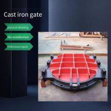
Cast Iron Copper-inlaid Square Gate for Canal Hydropower Station. Price of Syz1800 Cast Iron Gate


Related Products
-
 Shenyang Machine - Gate Integrated Steel GateUS$ 138.46 - 184.62MOQ: 1 Set
 -
Arc Steel Gates and Sliding Plane Steel Gates of Bortala Hydropower StationUS$ 1323.08 - 1353.85MOQ: 1 Set
-
Manufacturer of Steel Gates Produced in Mudanjiang - Mudanjiang Electric Non-rising Stem Steel GateUS$ 1323.08 - 1353.85MOQ: 1 Set
-
Henan Steel Gate Manufacturer, Brand of Steel Gates for Spillways in HenanUS$ 1323.08 - 1353.85MOQ: 1 Set
-
Lvliang Sewage Treatment - 304 Stainless Steel Gates, Steel Gates, Hand-electric Dual-purpose HoistsUS$ 138.46 - 184.62MOQ: 1 Set
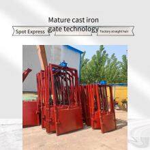
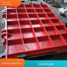
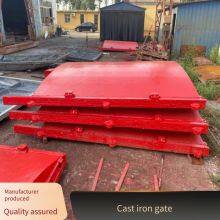
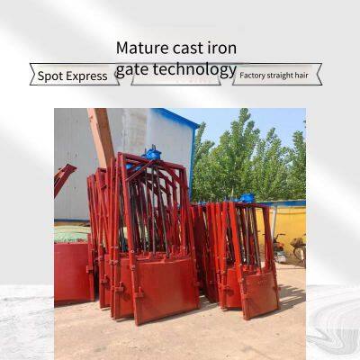
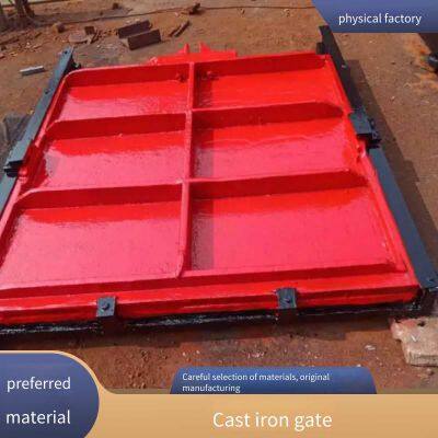
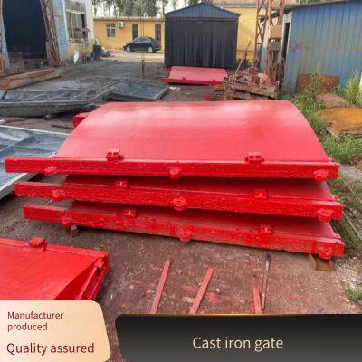
Water conservancy PZG high-pressure cast iron gate model @ Manufacturer of water conservancy cast iron gates with copper inlay @ Water conservancy double-seal cast iron gates. They are mainly used in water supply and drainage, hydropower, and water conservancy projects to cut off, dredge water flow, or adjust water levels. Cast iron gates have the following characteristics: 1. Strong structure, corrosion resistance, wear resistance, and easy installation. 2. Complete variety and wide adaptability. 3. Good sealing performance, water seepage: 0.72 (L/min.m) in the forward direction, (L/min.m) in the reverse direction. Cast iron gates are divided into planar cast iron gates and arched cast iron gates. Arched cast iron gates are mainly suitable for water sealing under forward pressure. Reverse water sealing gates can be manufactured according to user needs. In terms of structure, machined hard water sealing is adopted. Rubber water sealing can also be used for the bottom water sealing of larger gates. According to user requirements, copper or stainless steel inlay water sealing can be adopted. Water conservancy PZG high-pressure cast iron gate model @ Manufacturer of water conservancy cast iron gates with copper inlay @ Water conservancy double-seal cast iron gates. They are mainly used in water supply and drainage, hydropower, and water conservancy projects to cut off, dredge water flow, or adjust water levels. Cast iron gates have the following characteristics: 1. Strong structure, corrosion resistance, wear resistance, and easy installation. 2. Complete variety and wide adaptability. 3. Good sealing performance, water seepage: 0.72 (L/min.m) in the forward direction, (L/min.m) in the reverse direction. Cast iron gates are divided into planar cast iron gates and arched cast iron gates. Arched cast iron gates are mainly suitable for water sealing under forward pressure. Reverse water sealing gates can be manufactured according to user needs. In terms of structure, machined hard water sealing is adopted. Rubber water sealing can also be used for the bottom water sealing of larger gates. According to user requirements, copper or stainless steel inlay water sealing can be adopted.
Selection of cast iron gates
1. When selecting a gate, the H value (the height from the gate center to the bottom platform of the hoist) should be indicated;
2. The hoist should be determined according to the hoisting force and automation level in the table. For details, please refer to the hoist sample.
3. The design load of the platform should consider bearing in both forward and reverse directions (refer to the opening force for the closing force).
4. The shaft guide frame is set according to different well depths and should not interfere with the coupling during design;
5. When the whole screw, coupling, and gate plate move up and down during operation, it is an exposed stem gate. When the screw does not move and the gate plate moves up and down during operation, it is a concealed stem gate.
6. When selecting directional pressure-bearing gates, it should be specified. When the forward pressure-bearing gate is used to withstand water pressure in any direction, the water head should be
7. Non-rising stem gates are suitable for installation in manholes in scenic areas or in the middle of roads. This type of gate comes with its own opening device and does not require a *** hoist;
8. When placing an order, H should be specified, and the specific names, models, and specifications of the individual gates (and the supporting hoists) should be indicated;
9. Our factory can manufacture gates made of other materials (stainless steel, carbon steel, aluminum alloy, plastic) or special-shaped gates
Note: The tools necessary for installation are: electric welding machine (including power supply), gas cutting equipment, adjustable wrench, mobile crane, and lifting tools
Matters related to the installation of cast iron gates
1. Before installation, first check whether the connecting screws between the vertical frame and the horizontal frame, and between the gate plates (for gates composed of multiple gate plates) are loose due to transportation and handling. Check whether their joints are misaligned and adjust them to be in one plane. Check the gap between the gate plate and the gate slot. Ensure that the gap between the gate slot and the gate plate is no more than 0.08mm. If there is a gap, the closing device can be adjusted. Tighten all the connecting bolts.
2. During installation, vertically insert the entire gate into the reserved slot. Place adjustment pads under the two vertical frames (it is strictly prohibited to place pads under the crossbeam). Use a manual hoist and diagonal bracing to stabilize the two vertical frames. Make the gate straight and level. Insert anchor bolts into the anchor holes, adjust the position of the gate, support the formwork, and carry out the second-stage pouring.
3. When pouring concrete, the mortar flowing into the spaces between the gate plate, gate frame, wedges, and baffles should be completely removed to prevent the mortar from solidifying and affecting the opening and closing of the gate.
4. Remove the reinforcement. Before the gate leaves the factory, in order to make the gate plate and gate frame fit tightly and reduce the gap after installation, 4 - 6 closing device pressing irons are installed on the upper and lower frames of gates over 2m. Note that after adjusting the gap, the closing pressing irons should be removed to facilitate the opening and closing of the gate.
5. Reserve the installation positions for the gate and hoist as required in the embedded drawing;
6. Pre-embed the embedded parts using the plumb line method to ensure that their surface flatness and verticality are within the range of 1.5 - 3‰;
7. Fix the door frame and guide rails to the embedded parts with bolts;
8. When the slenderness ratio of the screw (lifting rod length / screw outer diameter) 4H/d > 200, a shaft guide frame should be installed. The distance between the shaft guide frame and the gate lifting lug should be greater than the gate opening.

Send Inquiry to This Supplier


You May Also Like
-
Manufacturer of Jiamusi Pgm Series Plane Steel GatesUS$ 1323.08 - 1353.85MOQ: 1 Set
-
Manufacturer of Ili Channel Sliding Planar Steel Gates and Rolling Steel GatesUS$ 138.46 - 184.62MOQ: 1 Set
-
Factory Sale of Cast Iron Gates, 2*2 Meters, River Gates, Steel Gates for ReservoirsUS$ 1200 - 1230.77MOQ: 1 Set
-
Manufacturer of Bidirectional Water-stop Cast Iron Gates, Water Pressure-resistant Channel GatesUS$ 692.31 - 707.69MOQ: 1 Set
-
2*2m Cast Iron Gate for Farmland Irrigation Channels in QinghaiUS$ 692.31 - 707.69MOQ: 1 Set
-
Hydraulic Dam, Movable Dam, Steel Sluice Dam, Manufacturer of Hydraulic Steel Dams, Discounts for Bulk OrdersUS$ 84615.38 - 89230.77MOQ: 1 Set
-
Hydraulic Lifting Dam, Steel Dam Gate, River Channel Treatment, Flood Control and Water Storage, Manufacturer of Landscape DamsUS$ 84615.38 - 89230.77MOQ: 1 Set
-
Guangxi Winch Hoist Steel Gate, Double-suspension-point Winch HoistUS$ 1200 - 1230.77MOQ: 1 Piece
-
[single-hoist Point Winch-type Hoist for Water Conservancy Projects, Small Footprint, Easy Maintenance]US$ 1200 - 1230.77MOQ: 1 Piece
-
Jinan Double-hoist Winch Hoist, Shandong Manufacturer of Fixed WinchesUS$ 1200 - 1230.77MOQ: 1 Piece


