








 Contact Platform Support
 Help Center
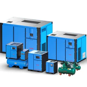
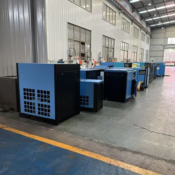
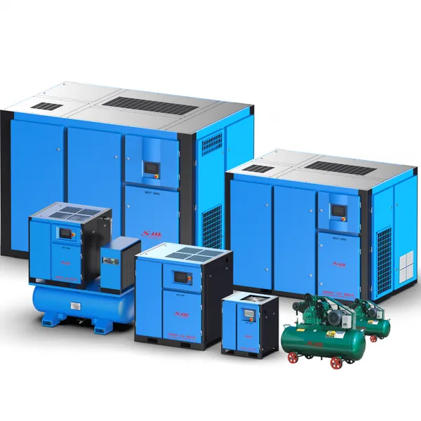
The Saman Screw Compressor Has Stable Performance and High Gas Output.






Related Products
-
 The Saman Mobile Screw Air Compressor is Easy to Operate, Highly Reliable and Has Good Power Balance.NegotiableMOQ: 1 Piece
 -
Saman Permanent Magnet Screw Air Compressor, Highly Efficient, Energy-saving, Low Rotational Speed, and High Gas Output CapacityNegotiableMOQ: 1 Piece
-
Saman Permanent Magnet Variable Frequency Screw Air Compressor, MV-100A, With a Power of 75KW, Highly Efficient and Energy-savingNegotiableMOQ: 1 Piece
-
Saman Screw Air Compressor, Permanent Magnet Variable Frequency, High-efficiency Double-stage Air CompressorNegotiableMOQ: 1 Piece
-
The Saman Screw Air Compressor is Widely Used and Can be Applied to Any Industry, Such as Food, Machinery, Healthcare, Industry, Mining, Etc.NegotiableMOQ: 1 Piece
Analysis of the Working Principle of Screw Air Compressors and the Working Principles of Their Various Systems
-
Main/ Motor System: The single screw air compressor, also known as the worm gear air compressor, has a meshing pair consisting of a 6-head screw and two 11-tooth star wheels. The worm gear simultaneously meshes with both star wheels, ensuring force balance for the worm gear while doubling the displacement. The type of screw compressor commonly referred to is generally the double screw type compressor.
The screw-type (also known as twin-screw) compressor has a pair of intermeshing and oppositely rotating spiral-shaped rotors. The rotors with raised surfaces are called the male rotor, while those with depressed surfaces are called the female rotor. As the rotors rotate within the housing, the working volume changes due to the insertion or withdrawal of the teeth, and thus the volume between each pair of rotor slots is periodically altered to achieve the purposes of suction, compression and exhaust.
The main unit is the core component of the screw machine. The structure and working principle of the main unit of any brand of screw machine are similar.
During the inhalation process, as the rotor rotates, one tooth of the rotor disk continuously detaches from one tooth slot of the rotor disk. The volume between the teeth gradually expands and is connected to the inhalation orifice. The gas enters the volume between the teeth through the inhalation orifice and continues until the volume between the teeth reaches its maximum value. At this point, it is disconnected from the inhalation orifice, and the volume between the teeth is sealed by the interaction of the teeth and the inner housing. The inhalation process ends. It is worth noting that at this time, the volume between the teeth of the rotor disk and the rotor disk itself are not connected to each other.
(2) During the compression process, the rotor continues to rotate. Before the volumes between the rotor teeth of the cathode and anode are connected, the gas in the volume between the rotor teeth of the anode is compressed first due to the intrusion of the rotor teeth of the cathode; after a certain rotation angle, the volumes between the rotor teeth of the cathode and anode are connected, forming a "V"-shaped pair of rotor tooth volumes (elementary volumes). As the two rotor teeth squeeze into each other, the elementary volumes are gradually shifted and the volume gradually decreases, achieving the compression process of the gas. The compression process continues until the elementary volume is connected to the exhaust port.
(3) During the exhaust process, as the rotor rotates, the volume of the element continuously decreases, and the compressed gas is sent to the exhaust pipe. This process continues until the volume reaches its minimum.
As the rotor continues to rotate, the above-mentioned suction, compression and exhaust processes occur in a continuous cycle. Each basic volume works successively, forming the working cycle of the screw-type refrigeration compressor.
From the analysis of the above process, the side where the two rotors rotate in harmony with each other, that is, the side where the protruding teeth and the recessed teeth fit and interlock with each other, the gas is compressed and forms a higher pressure, which is called the high-pressure zone; conversely, the side where the rotors rotate in opposite directions, that is, the side where the protruding teeth and the recessed teeth separate from each other, the volume between the teeth expands and forms a lower pressure, which is called the low-pressure zone. These two zones are separated by the contact lines of the casing and the rotors. It can be roughly considered that the planes of the axes of the two rotors are the interface between the high and low pressure zones. Additionally, the spiral-shaped channel formed by the meshing line between the male and female rotors enables the gas within the basic volume to be compressed while performing a spiral motion from the suction end to the exhaust end.
The screw compressor, as a type of rotary compressor, shares the characteristics of centrifugal compressors in its structure and belongs to the category of positive displacement compressors in its working principle.
Disadvantages: 1. The processing accuracy of the curved surface of the spiral rotor is very high; 2. The meshing lines between the rotors cannot achieve good inter-stage sealing, and are limited by factors such as rotor stiffness. Currently, screw compressors cannot reach a relatively high final pressure; 3. Due to the periodic high-speed passage of the medium through the suction and exhaust ports, as well as leakage through gaps, the compressor generates a lot of noise, and measures such as noise reduction and attenuation need to be taken; 4. Due to the above characteristics, screw compressors are generally applied in the following conditions: 1. The flow rate is not very high; 2. Long-term stable operation is required; 3. The exhaust pressure is not high.
Casing: Composed of the main body, the suction end seat, and the exhaust end seat, it is a key component of the compressor. The main body serves as the central component that connects all the parts, providing the correct assembly positions for each part and ensuring that the male and female rotors mesh correctly within the cylinder and operate reliably. Its end face shape is an "∞" shape, which is in line with the outer cylindrical surfaces of the two meshing rotors, enabling the rotors to be precisely installed inside the casing. Radial suction ports that meet the requirements of the rotor's rotation angle are set on the inner wall of the casing to ensure that the rotors can smoothly achieve the suction process during rotation.
The suction and exhaust end seats are sealing connection components located at the front and rear ends of the machine body. Besides serving as end face seals for the machine body, they are more importantly the assembly positions for the stator and rotor and the bearings that support the rotor.
Rotor: The main component for implementing variable capacitance compression, consisting of the male and female rotors. The tooth profile of the rotor is machined using high-precision special machines and special tools, and is one of the key parts of the compressor. The rotor profile is usually a unilateral non-symmetric cycloidal - arc profile. The male and female rotors have the following two structural methods:
The rotating part connected to the motor serves as the driving rotor, transmitting torque. At the same time, through the meshing relationship, it drives the rotating part (the driven rotor) to rotate.
2. The rotating parts (the male and female rotors) mesh with the driving gears driven by the motor through their respective driven gears, thereby transmitting torque.
Bearings: Bearings are components that support the stator and rotor of the motor and ensure the high-speed rotation of the rotor. Generally, ball bearings are used at the motor end to provide support. Additionally, when the rotor rotates and compresses the gas, an axial thrust is generated. To overcome this axial force, a tapered roller bearing is used at the other end of the rotor, which not only counteracts the axial force of rotor rotation but also withstands the radial force.
Most screw compressors adopt oil-injection type lubrication. The lubricating oil and the medium are mixed and enter the compressor, and the machine is lubricated and sealed as the medium flows. Its advantages are as follows: 1) Lower exhaust temperature. 2) Reduce working medium leakage and improve sealing effect. 3) Enhance lubrication of components and increase component lifespan. 4) Absorb and dampen sound waves, reducing noise. 5) Wash away mechanical impurities and reduce wear. However, due to the large amount of oil injection, an oil lubrication system must be added, and an oil-gas separator must also be installed at the compressor outlet. This will increase the volume and complexity of the unit. At the same time, for media that cannot tolerate contamination, this method cannot be used. Therefore, some screw compressors have oil-free lubrication inside.
The use of oil-free lubrication for the compressor imposes high requirements on the meshing clearance of the male and female rotors, the rigidity and mass of the rotors, as well as the processing quality of the entire unit.
-
Motor system: • The main unit is connected to the motor - rigid connection • Transmission method - gear transmission

Send Inquiry to This Supplier


You May Also Like
-
Saman Screw Air Compressor MV Permanent Magnet Variable Frequency Series, With Flow Rates Ranging From 1m³ to 60m³NegotiableMOQ: 1 Piece
-
Saman Screw Air Compressor, Highly Efficient and Energy-saving, With a Wide Range of Models and Excellent Environmental Protection Features.NegotiableMOQ: 1 Piece
-
Saman Permanent Magnet Variable Frequency Screw Air Compressor MV-150A, With a Power of 110KW and a Flow Rate of 20m³NegotiableMOQ: 1 Piece
-
The Saman Mobile Screw Air Compressors Can be Divided Into Diesel Mobile Screw Air Compressors and Electric Mobile Screw Air Compressors.NegotiableMOQ: 1 Piece
-
Saman Screw-type Air Compressor, Permanent Magnet Variable-frequency Air Compressor, Double-stage Compression Screw Air CompressorNegotiableMOQ: 1 Piece
-
Saman Permanent Magnet Variable Frequency Screw Air Compressor MV-150ANegotiableMOQ: 1 Piece
-
Saman Screw Air Compressor Manufacturer Directly Sells Products. There Are a Wide Variety of Models and Complete Series Available.NegotiableMOQ: 1 Piece
-
Saman Permanent Magnet Variable-frequency Screw Air CompressorNegotiableMOQ: 1 Piece
-
Saman MV-10A Permanent Magnet Variable Frequency Screw Air CompressorNegotiableMOQ: 1 Piece
-
MA-10A Saman Screw-type Air CompressorNegotiableMOQ: 1 Piece


