

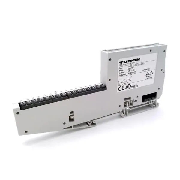
TURCK BL20-16DI-24VDC-P Economy Module

Related Products
-
 TURCK MK33-LI-EX0 Intrinsically Safe Level SwitchNegotiableMOQ: 1 Piece
 -
TURCK MK35-LI-EX0 Intrinsically Safe Level SwitchNegotiableMOQ: 1 Piece
-
VMIC VMIVME-7452 Research TechnologiesNegotiableMOQ: 1 Piece
-
VEXTA PH266-01GK-C5 2-Phase Stepping MotorsNegotiableMOQ: 1 Piece
-
IDEC RU4S-D24 General Purpose RelayNegotiableMOQ: 1 Piece
I. Overview
TURCK BL20-16DI-24VDC-P is a distributed digital input module of the BL20 series, specifically designed for signal acquisition in industrial automation control systems. Its core function is to convert 24VDC digital signals output by field sensors (such as proximity switches, photoelectric switches, and limit switches) into bus-transmittable data, which is then uploaded to PLCs or controllers to realize equipment status monitoring and logic control. Adopting a modular design, this module is compatible with various industrial buses including Profinet, EtherNet/IP, and Modbus (when used with BL20 series gateways), supports hot-swap and expansion configurations, and has an IP20 protection rating. It is widely used in production line monitoring and equipment interlock control scenarios in industries such as automotive manufacturing, logistics and warehousing, mechanical processing, and energy and chemical engineering.
II. Key Features
Multi-Channel Signal Acquisition
High Reliability & Anti-Interference Design
Comprehensive Diagnosis & Status Feedback
Flexible Expansion & Compatibility
Easy Installation & Maintenance
III. Technical Specifications
IV. Working Principle
Signal Acquisition
Signal Conditioning
Digitalization & Logic Processing
Bus Transmission
Diagnosis & Protection
V. Operation Guide
Installation Steps
Installation Environment
Physical Installation
Wiring Specifications
2. Software Configuration (Based on Turck IP-Address Tool + PLC Programming Software)
Gateway Configuration
Module Recognition & Parameter Configuration
Download & Activation
3. Operation & Maintenance
Status Monitoring
Hot-Swap Operation
Regular Maintenance
4. Common Troubleshooting

Send Inquiry to This Supplier


You May Also Like
-
IDEC PFJ-T081U Relay Output ModuleNegotiableMOQ: 1 Piece
-
IDEC PF3S-HSC1 Touchscreen HMI ModuleNegotiableMOQ: 1 Piece
-
IDEC PF3S-T32K Output ModuleNegotiableMOQ: 1 Piece
-
IMS MX-CS100-401 Control ModuleNegotiableMOQ: 1 Piece
-
IMS MX-CS101-701 Control ModuleNegotiableMOQ: 1 Piece
-
Bombardier DCC2223A 3EST125-977 Drive Control UnitNegotiableMOQ: 1 Piece
-
Fireye 85UVF1A-1QD Flame DetectorNegotiableMOQ: 1 Piece
-
Cameron AAP3798102-00130 Operation PanelNegotiableMOQ: 1 Piece
-
ABSOLUTE MOX12-P3509 Power ModuleNegotiableMOQ: 1 Piece
-
ACQUISITIONLOGIC AL81G High-Performance Data Acquisition ModuleNegotiableMOQ: 1 Piece


