Material
Other, Global universal model
Condition
Other, Global universal model
Task
Other, Global universal model
Mathematical Model
Other, Global universal model
Signal
Other, Global universal model
Customized
Non-Customized
Structure
Other, Global universal model
Operating Temperature
-40℃~+85℃
Relative Humidity
5%-95% (non-condensing)
Dimensions
100mm×160mm×233mm
I. Overview
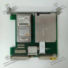
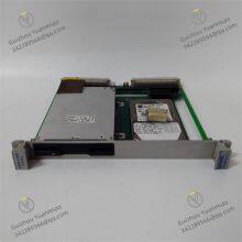
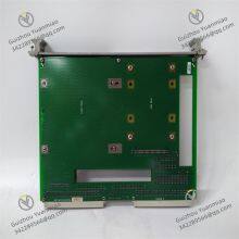
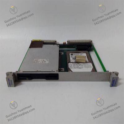
VMIC VMIVME-7452 is a multi-channel analog input module based on the VMEbus architecture, specifically designed for high-precision signal acquisition requirements in industrial embedded control systems. Its core function is to convert analog signals (voltage/current type) output by field sensors (such as temperature, pressure, and flow sensors) into digital signals, which are transmitted to VME controllers/CPU modules via the VMEbus to realize real-time acquisition, monitoring, and analysis of industrial process parameters. Adopting a 3U VME standard package, this module features high resolution, wide range adaptability, and strong anti-interference capabilities. It is compatible with the VME 64x bus specification, supports multiple trigger modes and calibration functions, and is widely used in scenarios requiring strict signal acquisition accuracy and stability, such as aerospace testing, industrial automation measurement and control, energy monitoring, and medical equipment. It serves as a core component for analog signal acquisition in embedded control systems.

II. Key Features
Multi-Channel High-Precision Acquisition
Equipped with 16 single-ended / 8 differential analog input channels (switchable via software configuration), with a single-channel resolution of 16 bits, ensuring the delicacy and accuracy of signal acquisition to meet high-precision measurement and control requirements.
Supports wide-range signal input: voltage modes (±10V, ±5V, ±2.5V, 0-10V, etc.) and current modes (4-20mA, 0-20mA). No hardware jumpers are required; it can be flexibly configured via software to adapt to different types of sensors.
Flexible Trigger & Sampling Control
Supports multiple sampling trigger modes: software trigger, external hardware trigger, timer trigger, and bus trigger. Can be flexibly selected according to application scenarios (e.g., continuous sampling, event-triggered sampling) to adapt to complex measurement and control logic.
The sampling rate is programmable. The maximum sampling rate of a single channel is 100kSps (differential mode), and the synchronous sampling rate of all channels is 50kSps, which can capture fast-changing dynamic signals (such as transient pressure and pulse flow).
High Isolation & Anti-Interference Design
Achieves 250V AC optoelectronic isolation between input channels and the VMEbus, with mutual isolation between channels, effectively avoiding bus interference and signal crosstalk, and ensuring stable signal acquisition in strong electromagnetic environments.
Built-in analog signal filter circuit (low-pass filter), the filter cutoff frequency (1Hz~10kHz) can be configured via software to suppress high-frequency noise interference; electromagnetic compatibility (EMC) performance complies with MIL-STD-461 and EN 55022 standards, adapting to harsh industrial environments.
Intelligent Calibration & Data Processing
Supports dual calibration modes: software self-calibration and external reference calibration. Built-in calibration coefficient storage unit (EEPROM), which can initiate zero calibration and gain calibration via software, ensuring the stability of acquisition accuracy during long-term use without disassembling the module.
Built-in FIFO data buffer (depth ≥4k samples) can temporarily store collected data to avoid data loss, support batch data transmission, and reduce bus communication load; supports data format conversion (binary/BCD code), directly adapting to the data processing needs of controllers.
Efficient VMEbus Compatibility
Strictly complies with the VME 64x bus specification, supports A16/A24/A32 address space addressing and D8/D16/D32 data transmission modes, and is compatible with mainstream VME controllers (such as Motorola 68000 series and PowerPC series VME CPUs).
Supports VMEbus interrupt function. Events such as completion of acquisition, full data buffer, and fault alarm can trigger interrupt requests, enabling rapid response to controller processing and improving system real-time performance.
High Reliability & Industrial-Grade Adaptability
Adopts industrial-grade components and rugged packaging design, with a wide operating temperature range (-40℃~+85℃), capable of withstanding temperature fluctuations and vibration impacts in extreme environments. The Mean Time Between Failures (MTBF) exceeds 500,000 hours.
Built-in overvoltage, overcurrent, and short-circuit protection circuits. When the input signal exceeds the range or is short-circuited, it automatically cuts off the channel to protect the module without affecting the operation of other channels, improving the safety of system operation.
III. Technical Specifications
IV. Working Principle
The core working logic of the VMIVME-7452 is "Analog Signal Acquisition → Signal Conditioning → A/D Conversion → Data Buffering → Bus Transmission + Status Monitoring," with the specific process as follows:
Signal Acquisition & Configuration
Analog signals (voltage/current) output by field sensors are connected to the module's input channels via terminals. The module determines the signal processing rules according to the software-configured channel mode (single-ended/differential) and input range (e.g., ±10V, 4-20mA).
Signal Conditioning
The input signal first passes through the front-end protection circuit (overvoltage/overcurrent protection), then enters the Programmable Gain Amplifier (PGA). The signal gain is adjusted according to the range configuration to amplify weak signals to the adaptive range of the A/D converter; at the same time, high-frequency noise is suppressed through a low-pass filter to ensure signal stability.
A/D Conversion
The conditioned analog signal is sent to a 16-bit high-precision Analog-to-Digital Converter (ADC). Digital conversion is completed under the action of a trigger signal (software/hardware/timer trigger), and the converted digital signal is temporarily stored in an internal register.
Data Buffering & Processing
After verification, the digital signal is written into the FIFO data buffer to avoid data loss caused by bus transmission delay; the module's microcontroller real-time monitors the buffer status. When the data volume reaches the set threshold or sampling is completed, an interrupt request is sent to the controller via the VMEbus.
Bus Transmission & Calibration
After responding to the interrupt, the controller reads the collected data in the FIFO via the VMEbus; at the same time, the module supports software calibration commands. The controller can issue calibration commands to correct zero and gain errors through the internal reference circuit, ensuring long-term acquisition accuracy.
Status Monitoring & Protection
The module has a built-in status detection circuit that real-time monitors the input signal range, power supply voltage, and bus communication status. If faults such as over-range, short circuit, or power supply abnormality are detected, an alarm is immediately triggered and fed back to the controller via the bus, and the faulty channel is cut off to protect the module.
V. Operation Guide
Installation Steps
Installation Environment
Install in a standard 3U VME chassis, ensuring good ventilation of the chassis and keeping away from high-temperature heat sources and strong electromagnetic interference sources; the chassis must be reliably grounded (ground resistance ≤4Ω) to enhance anti-interference capabilities and equipment safety.
Physical Installation
Insert the module into the slot along the VME chassis rail, ensuring that the module's gold fingers are fully in contact with the chassis backplane slot, and tighten the fixing screws at the front of the module to avoid poor contact caused by vibration; the distance between adjacent modules must meet the chassis heat dissipation requirements (recommended ≥10mm).
Wiring Specifications
Power Wiring: The module automatically obtains +5V and ±12V power through the VME backplane, no additional wiring is required; ensure the normal power output of the chassis backplane.
Signal Wiring: Connect the sensor signal wires to the terminal block at the front of the module. In single-ended mode, connect the signal "+" to the corresponding channel terminal and the signal "-" to the common ground; in differential mode, distinguish the positive and negative poles of the channel (e.g., CHx+, CHx-) to avoid reverse connection.
Shielding Wiring: Ground one end of the sensor shielded wire (single-point grounding) and connect the other end to the module's shielding terminal to reduce electromagnetic interference; ensure the normal power supply of the loop for current signals (externally powered sensors need to be connected to a 24VDC power supply separately).
2. Software Configuration (Based on VME Controller Development Platform)
Module Recognition & Initialization
In the VME controller development software (such as VMIC VMIPRO, Wind River Workbench), identify the VMIVME-7452 module through VMEbus address addressing, load the corresponding driver, and complete module initialization (such as bus communication parameter configuration and interrupt vector assignment).
Channel Parameter Configuration
Configure Channel Mode: Switch between single-ended/differential input.
Set Input Range: Select voltage/current range (e.g., 4-20mA, ±5V) according to the sensor type.
Configure Filter Parameters: Set the low-pass filter cutoff frequency (1Hz~10kHz) to suppress noise.
Select Trigger Mode: Software trigger (start sampling via programming commands), external trigger (connect external trigger signal to the TRIG terminal), timer trigger (set sampling interval).
Calibration Operation
Start the software self-calibration function. The module automatically corrects zero and gain errors through internal reference signals, and the calibration coefficients are stored in the EEPROM; for higher accuracy, external standard signals (such as standard voltage sources and current sources) can be connected for external calibration, and the calibration coefficients can be adjusted manually.
Sampling & Data Reading
Issue sampling commands via programming. The module starts sampling according to the configured mode, and the collected data is stored in the FIFO buffer; when the buffer is full or sampling is completed, the module triggers an interrupt, and the controller reads the data through the interrupt service routine for subsequent processing (such as storage, analysis, and display).
3. Operation & Maintenance
Status Monitoring
Real-time monitor the module's working status through development software, including channel sampling data, FIFO buffer status, number of interrupt triggers, and fault alarm information (such as over-range, short circuit); there is no alarm prompt during normal operation, and a software alarm pop-up window or indicator light flashes when a fault occurs.
Data Verification
Regularly verify the acquisition accuracy through standard signal sources (such as 4mA, 20mA standard current, 0V, 10V standard voltage). If the deviation exceeds ±0.01% of the full scale, re-perform the calibration operation.
Regular Maintenance
Inspect the module's wiring terminals for looseness and the reliability of shielded wire grounding every 6 months; clean the dust on the module surface to ensure unobstructed heat dissipation.
Perform full-channel calibration every 1 year and update the calibration coefficients to ensure long-term acquisition accuracy.
Avoid severe vibration or impact on the module; it is prohibited to plug/unplug the module under power. Turn off the VME chassis power before maintenance.
4. Common Troubleshooting