Material
Other, Global universal model
Condition
Other, Global universal model
Task
Other, Global universal model
Mathematical Model
Other, Global universal model
Signal
Other, Global universal model
Customized
Non-Customized
Structure
Other, Global universal model
Operating Temperature
-10℃~+50℃
Relative Humidity
5%-95% (non-condensing)
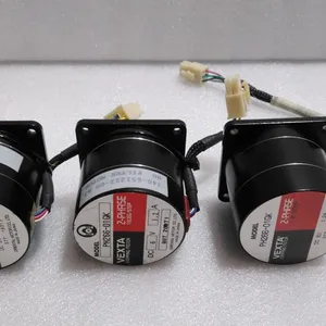
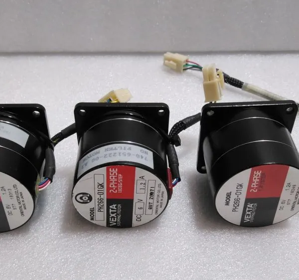
I. Overview
VEXTA PH266-01GK-C5 is a 2-phase stepping motor whose core function is to convert electrical pulse signals into precise angular displacement or linear displacement. By cooperating with a stepping driver, it realizes open-loop precision transmission without sensor feedback, meeting the positioning and execution requirements of scenarios such as automated production lines, CNC machine tools, medical equipment, and electronic devices. Adopting a 2-phase excitation structure, this motor features high torque density, low vibration, and stable operation. Equipped with a standard mounting flange and shaft end design, it is compatible with the full range of VEXTA stepping drivers (such as UDK5128N, DME25SF, etc.). Widely used in scenarios requiring strict positioning accuracy and operational stability, such as printing machinery, cutting equipment, conveyor line positioning, and precision workbench driving, it serves as a core executive component in industrial precision transmission systems.
II. Key Features
High-Precision Positioning Performance
Adopts the classic structure of a 2-phase stepping motor, with a step angle of 1.8° (full-step mode). Higher resolution can be achieved under microstepping drive (e.g., 0.1125° step angle at 16 microsteps), ensuring positioning accuracy within ±0.05° to meet the position control requirements of precision equipment.
No cumulative positioning error. Precise positioning can be achieved in open-loop control mode without encoder feedback, simplifying the system architecture and reducing integration costs. Suitable for cost-sensitive applications with moderate precision requirements.
High Torque & Dynamic Performance
Rated holding torque reaches 6.0N·m (typical value), and the starting torque is close to the holding torque, enabling stable driving of medium-load equipment (such as precision workbenches and small conveying mechanisms) and avoiding startup slip or step loss.
Low vibration and noise during low-speed operation. Through optimized magnetic circuit design and rotor structure, the common "resonance phenomenon" of stepping motors is suppressed. It operates stably in the low-speed range of 50-500rpm, suitable for equipment requiring a low-noise environment (such as medical testing equipment and electronic assembly machines).
High Reliability & Long-Life Design
Uses high-quality permanent magnet materials and precision bearings, with moderate rotor inertia (180g·cm² typical value), fast acceleration response, and support for frequent startup/shutdown and forward/reverse switching, meeting the high-frequency action requirements of automated equipment.
The motor windings adopt Class F insulation material, with a heat resistance temperature of 155℃ and strong stability during continuous operation. The brushless wear-free design ensures a Mean Time Between Failures (MTBF) of over 20,000 hours, reducing maintenance frequency and costs.
Flexible Adaptability & Installation Compatibility
Compatible with the full range of VEXTA 2-phase stepping drivers, supporting multiple driving modes such as constant current drive and microstepping drive. Operational performance (such as microstep level and current limit) can be adjusted through driver parameter configuration to adapt to different load and speed requirements.
Adopts standard flange mounting dimensions (60mm square flange), with a plain shaft design at the shaft end (keyway-equipped model optional). Supports horizontal/vertical installation, adapting to the installation space layout of most industrial equipment with strong replaceability.
Wide Voltage & Environmental Adaptability
Adapts to a wide range of driving voltages (24VDC-110VDC depending on driver configuration). The typical rated current of the windings is 3.0A per phase, and the output current can be adjusted through the driver to balance torque and power consumption.
Operating temperature range: -10℃~+50℃; storage temperature range: -20℃~+80℃; humidity: 5%-90% (non-condensing); protection class: IP40. It can adapt to temperature and humidity fluctuations in general industrial environments.
III. Technical Specifications

IV. Working Principle
As a hybrid stepping motor, the core working logic of VEXTA PH266-01GK-C5 is "Electrical Pulse Signal → Winding Excitation → Reluctance Torque → Precise Step Movement + Continuous Rotation", with the specific process as follows:
Signal Reception & Excitation Control
The stepping driver receives pulse signals (direction signal + pulse signal) output by the controller (such as PLC, motion control card). According to the pulse frequency and quantity, it controls the on-off sequence and current magnitude of the motor's A and B phase windings (constant current drive mode).
Magnetic Circuit Formation & Torque Generation
When the motor stator windings are energized, an alternating magnetic field is generated, forming magnetic coupling with the permanent magnets on the rotor. By alternately switching the excitation state of the A and B phase windings (e.g., "AB→B→BA→A→AB" cycle in full-step mode), continuous reluctance torque is generated based on the minimum reluctance principle, driving the rotor to rotate step by step.
Step Angle & Speed Control
Each received pulse signal causes the rotor to rotate by a fixed step angle (1.8° for full-step). The pulse frequency determines the motor speed (higher frequency means faster speed, with a typical speed range of 0-3000rpm); the number of pulses determines the rotation angle (e.g., 200 pulses correspond to 360° rotor rotation), achieving precise position control.
Microstepping Drive Optimization
When the driver enables the microstepping function, it outputs stepped current to the windings, enabling smooth transition of the stator magnetic field and reducing the rotor step angle (e.g., 0.1125° per step at 16 microsteps). This effectively suppresses low-speed resonance and improves operational stability and positioning accuracy.
Holding Torque Characteristic
When no pulse signal is input, the driver continuously provides static current to the windings. The stator magnetic field locks the rotor in the current position, generating a holding torque (6.0N·m) to prevent position deviation caused by external load forces, realizing positioning holding without motor braking.
V. Operation Guide
Installation Steps
Installation Environment
Select a dry and well-ventilated installation location for the equipment, away from high-temperature heat sources (such as motors, frequency converters) and strong magnetic field interference sources. The mounting surface must be flat and sturdy to ensure no vibration or loosening after the motor is fixed.
Mechanical Installation
Fix the motor flange to the equipment mounting base with M5 bolts (recommended torque: 2.5N·m). The mounting surface must fit the flange end face to avoid vibration caused by gaps.
When connecting the output shaft to the load (such as a coupling, gear), the coaxiality error shall be ≤0.1mm and the end runout ≤0.05mm to avoid shaft system wear or torque loss due to installation deviation.
Do not strike the motor shaft end. Handle the load gently during installation to prevent damage to bearings and the rotor.
Wiring Specifications
The motor windings have 4 lead wires (Phase A: red/black, Phase B: white/blue, subject to the product nameplate). Connect them to the corresponding terminals of the driver (A+ to red, A- to black, B+ to white, B- to blue). Do not reverse or short-circuit the wires.
Use AWG 14-16 gauge wires for wiring. Tighten the terminal screws to avoid poor contact. The distance between the motor and the driver shall be ≤2m. If the cable needs to be extended, use shielded wires to reduce interference.
2. Driver Configuration & Debugging
Driver Selection
C
ore Parameter Configuration
Current Setting: According to the load requirements, set the output current through the driver's potentiometer or software (it is recommended to set it to 70%-100% of the motor's rated current; reduce the current during light load to reduce heat generation).
Microstep Level: Select the microstepping mode according to the positioning accuracy requirements (e.g., 16 microsteps for high-precision positioning, 2 microsteps for high-speed operation).
Decay Mode: Adjust the current decay mode according to the speed (fast decay for high speed, slow decay for stable low-speed operation).
Commissioning & Trial Operation
After powering on, send low-speed pulse signals (e.g., 100rpm) through the controller, and observe whether the motor operates stably without obvious resonance or noise.
Test Positioning Accuracy: Send a fixed number of pulses (e.g., 200 pulses corresponding to 360°), and check whether the actual rotation angle of the motor is consistent with the theoretical value. If step loss occurs, increase the driver current or reduce the operating speed.
3. Operation & Maintenance
Status Monitoring
Regularly check the motor temperature (normal operating temperature ≤80℃), vibration, and noise during operation. If abnormal heating (exceeding 90℃) or abnormal noise occurs, stop the machine to check the wiring, load, or driver parameters.
Load Matching
Regular Maintenance
Inspect the wiring terminals for looseness and the flange fixing bolts for tightness every 6 months. Clean the dust on the motor surface.
Check the shaft system operation status every year. If shaft end looseness or increased rotation resistance occurs, replace the bearings (it is recommended to contact the original factory for maintenance).
For long-term idleness (more than 3 months), power on and run the motor for 10 minutes every month to avoid bearing rust and winding moisture.
4. Common Troubleshooting