

Home > Electrical & Electronics > Electrical Control System > Cameron AAP3798102-00130 Operation Panel
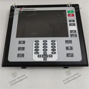
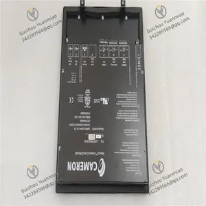
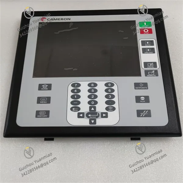
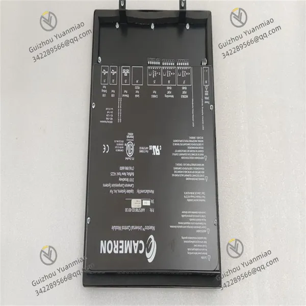
Cameron AAP3798102-00130 Operation Panel
Negotiable
MOQ: 1 Piece (Price negotiable depending on order volume and customization)
Key Specifications
Get Latest Price
Material:
Other, Global universal model
Condition:
Other, Global universal model
Task:
Other, Global universal model
Payment & Shipping
Payment Methods:
Port of Shipment:
China
Delivery Detail:
Delivery time depends on order quantity.
Related Products
-
 ABSOLUTE MOX12-P3509 Power ModuleNegotiableMOQ: 1 Piece
 -
ACQUISITIONLOGIC AL81G High-Performance Data Acquisition ModuleNegotiableMOQ: 1 Piece
-
ALPHA SP060S-MF2-20-1C1-2S Planetary GearboxNegotiableMOQ: 1 Piece
-
Bachmann MPC270-128512M Communication ModuleNegotiableMOQ: 1 Piece
-
Autoliv Sim.Mod. B0760 627913600B Regulator ModuleNegotiableMOQ: 1 Piece
Material
Other, Global universal model
Condition
Other, Global universal model
Task
Other, Global universal model
Mathematical Model
Other, Global universal model
Signal
Other, Global universal model
Customized
Non-Customized
Structure
Other, Global universal model
Dimensions
200 x 150 x 80 mm
Weight
2kg
Resolution
±0.1%

Send Inquiry to This Supplier

* Email
Want the best price?
Post an RFQ now!

Business Type
Trading Company
Year Established
2014
Factory Size
1,000-3,000 square meters
Product Certifications
SA8000
You May Also Like
-
Autoliv Gtw.Mod. B0110 627697900B Gateway ModuleNegotiableMOQ: 1 Piece
-
BERTHOLD LB4460 Communication ManagerNegotiableMOQ: 1 Piece
-
BRAKE BCC-1 Braking Control ModuleNegotiableMOQ: 1 Piece
-
Bristol Babcock 396352-01-4 Analog Input ModuleNegotiableMOQ: 1 Piece
-
Baumuller BUM61-20 Servo DriverNegotiableMOQ: 1 Piece
-
Basler DECS-200-1L Digital Excitation ControllerNegotiableMOQ: 1 Piece
-
DEIF DELOMATIC-3 Printed Circuit BoardNegotiableMOQ: 1 Piece
-
DEIF SCM4.1 Printed Circuit BoardNegotiableMOQ: 1 Piece
-
EATON MP3010 Motor Protection RelayNegotiableMOQ: 1 Piece
-
EATON XV-440-10TVB-1-20 Touch Screen ControllerNegotiableMOQ: 1 Piece


