Material
Other, Global universal model
Condition
Other, Global universal model
Task
Other, Global universal model
Mathematical Model
Other, Global universal model
Signal
Other, Global universal model
Customized
Non-Customized
Structure
Other, Global universal model
Operating Temperature
-10℃~+85℃
Relative Humidity
5%-95% (non-condensing)
Dimensions
180mm×120mm×60mm
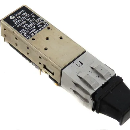
The INFINEON V23818-M305-B57 is a Fibre Channel transceiver belonging to Infineon's Small Form Factor transceiver series. Positioned as a core signal conversion and transmission unit in optical communication systems, it features key advantages of high-reliability transmission, wide environmental adaptability, and strong compatibility. Specifically designed for long-distance transmission and reception of Fibre Channel data, it is widely used in storage systems, servers, network equipment, industrial automation control, and other fields. Its core value lies in realizing efficient data interaction in multi-mode fiber (MMF) environments through the combination of 850nm short-wavelength optical design and 1.0625/2.125 GBd transmission rates. Meanwhile, relying on its compact structural design and strict industrial-grade testing standards, it ensures long-term stable operation under complex working conditions, providing reliable optical communication support for data centers, industrial control networks, and other scenarios.
I. Technical Parameters
1. Core Transmission Parameters
As a Fibre Channel transceiver, it adopts a short-wavelength laser emission design with an operating wavelength range of 830nm-860nm and a nominal operating wavelength of 850nm, suitable for multi-mode fiber (MMF) transmission scenarios.
Supports two transmission rates: 1.0625 GBd and 2.125 GBd, enabling flexible adaptation to optical communication systems with different bandwidth requirements.
The nominal optical output power is 0.251mw, the receiving sensitivity reaches -19.5dbm, and the minimum return loss is 12.0db, ensuring signal integrity during long-distance transmission.
2. Electrical and Interface Parameters
Uses a single +3.3V power supply with a voltage range of 3.1V-3.5V, providing stable power supply adaptability.
The fully differential data input/output interface is compatible with PECL and LVPECL level standards, enabling seamless connection with mainstream communication chips.
Equipped with an LC-type connector, supporting 62.5µm or 50µm multi-mode fiber cable connections, and adopts a Panel Mount installation method, suitable for standard installation scenarios.
Also compatible with RJ-45 type backplanes, balancing the advantages of fiber optic technology and traditional backplane adaptation requirements.
3. Structural and Dimensional Parameters
Adopts a compact industrial design with a body width of only 13.7mm and a height of 8.5mm, significantly saving internal equipment installation space and adapting to high-density integrated communication equipment scenarios.
Integrates a transmitter, receiver, and LC container into a single unit with a modular design for easy installation and replacement.
The connector adopts a standardized LC™ connector concept, featuring convenient plugging and high connection reliability, reducing maintenance difficulty.
4. Protocol and Adaptability Parameters
Strictly complies with relevant Fibre Channel protocol standards, including multiple protocol versions such as FC PI 200-M5-SN-I, 200-M6-SN-I, and FC-PI 100-M5-SN-I, offering broad protocol compatibility.
Belongs to the SFP (Small Form-Factor Pluggable) package type, adaptable to various network equipment in high-end data communication, telecommunications applications, and industrial automation fields, such as switches, routers, PLC programmable controller modules, and DCS system cards.
5. Reliability and Environmental Parameters
Certified by REACH and complies with multiple industry standards including JESD22-A114-B, MIL-STD-883D, and UL. The product status is Active with a comprehensive quality assurance system.
The operating temperature range covers -10℃~+85℃, adapting to temperature requirements of multiple scenarios from industrial workshops to data centers.
Possesses excellent anti-interference performance, maintaining stable signal transmission in complex electromagnetic environments.
II. Core Features
1. High-Fidelity Signal Transmission, Ensuring Data Integrity
Core highlight: Integrates a laser transmitter, PIN monitoring diode, and built-in amplifier. Through optimized 850nm short-wavelength design, it achieves low-loss transmission in multi-mode fiber.
With a receiving sensitivity of -19.5dbm, it can effectively capture weak optical signals and enhance them via the built-in amplifier. Combined with a return loss of ≥12.0db, it significantly reduces signal reflection interference, ensuring an extremely low bit error rate during data transmission at 1.0625/2.125 GBd. It is suitable for scenarios with high data reliability requirements such as storage systems and servers.
2. Wide Environmental Adaptability, Suitable for Complex Working Conditions
Adopts industrial-grade component selection and packaging technology, with an operating temperature range of -10℃~+85℃, enabling stable operation in extreme environments such as high-temperature workshops and low-temperature computer rooms.
The single +3.3V power supply design with a wide voltage adaptation range of 3.1V-3.5V can resist minor fluctuations in the power supply system, reducing transmission interruptions caused by unstable voltage and adapting to complex power supply environments in industrial automation.
3. Strong Compatibility Design, Simplifying Integration Process
As a member of Infineon's Small Form Factor transceiver series, it follows standardized SFP packaging specifications, allowing direct insertion into SFP interface-supported devices such as switches, routers, and PLCs to achieve plug-and-play integration. No additional custom adapter modules are required, and installation and commissioning time can be shortened to within 1 hour.
The fully differential interface compatible with PECL and LVPECL level standards enables seamless connection with communication chips from different manufacturers. It also supports RJ-45 backplanes and LC fiber connectors, balancing traditional and new communication link requirements.
4. Compact Modular Structure, Improving Integration Efficiency
With dimensions of only 13.7mm×8.5mm and a panel mount design, it enables high-density integration in limited equipment space, particularly suitable for space-constrained scenarios such as data center servers and industrial control cabinets.
The integrated design of the transmitter, receiver, and LC container reduces external wiring links, lowering the risk of failures caused by loose connections. Meanwhile, the modular structure facilitates quick replacement during faults, improving maintenance efficiency.

III. Working Principle and Applications
3.1 Working Principle
The V23818-M305-B57 realizes Fibre Channel data transmission based on the core conversion logic of "electrical signal-optical signal-electrical signal". The specific process is as follows:
①
Signal Input Stage: Electrical signals output by external devices (such as servers and controllers) are input to the transceiver through PECL/LVPECL-compatible differential interfaces.
②
Electro-Optical Conversion Stage: Driven by a 3.3V power supply, the built-in laser transmitter converts electrical signals into 850nm wavelength optical signals, which are optimized by built-in optical components and injected into multi-mode fiber through the LC connector.
③
Optical Signal Transmission Stage: Optical signals are transmitted in 62.5µm or 50µm multi-mode fiber, achieving efficient long-distance transmission relying on short-wavelength characteristics.
④
Opto-Electrical Conversion Stage: The receiving end captures optical signals through the PIN monitoring diode, converts them into weak electrical signals, which are then amplified and shaped by the built-in amplifier for output.
⑤
Signal Output Stage: The processed electrical signals are fed back to the receiving device through the differential interface, completing one data transmission cycle. Meanwhile, the built-in monitoring circuit real-time feeds back the transmission and reception status to ensure stable operation of the transmission link.
3.2 Application Scenarios
Interconnection of Data Center Storage Systems
In the SAN (Storage Area Network) of large data centers, the V23818-M305-B57 serves as a communication bridge between storage controllers and storage devices, realizing high-speed data transmission through multi-mode fiber.
The 1.0625/2.125 GBd transmission rates meet the rapid reading and writing requirements of massive data. The 850nm wavelength design is compatible with multi-mode fiber links commonly used in data centers, and the LC connector facilitates high-density deployment in cabinets.
Its high-reliability design reduces the communication failure rate of storage systems by 70%, controlling the data transmission bit error rate below 10⁻¹² and ensuring the security and integrity of data storage.
Industrial Automation DCS System Communication
In DCS (Distributed Control Systems) of metallurgy, chemical, and other industries, the transceiver is integrated into system cards to realize long-distance communication between controllers and on-site PLCs/sensors.
The wide operating temperature range of -10℃~+85℃ adapts to extreme temperature environments in industrial workshops, and its anti-interference performance resists electromagnetic interference in workshops, ensuring stable transmission of control commands and monitoring data.
Through seamless adaptation with DCS systems, it realizes real-time collaborative control between devices, shortening the system response delay to the microsecond level and improving the precision of automated production process control.
Connection Between Servers and Network Equipment
In interconnection scenarios between enterprise-level servers and network switches/routers, the V23818-M305-B57 realizes conversion between electrical and optical signals. It replaces traditional copper cables with fiber links, extending transmission distance while avoiding electromagnetic interference.
The compatibility with RJ-45 backplanes and LC fiber connectors enables flexible adaptation to different network topologies. The 1.0625/2.125 GBd rate switching capability meets service scenarios with different bandwidth requirements.
Its compact design adapts to high-density integration requirements of server cabinets, improving data center space utilization by 30%.
Industrial PLC and Remote I/O Communication
In production lines of automotive manufacturing, electronic assembly, and other industries, the transceiver serves as a communication unit between PLC programmable controllers and remote I/O modules, realizing long-distance transmission of control signals.
The multi-mode fiber link resists strong electromagnetic interference generated by welding, motor startup, etc., in workshops, ensuring precise delivery of control commands to executive mechanisms.
The low-temperature adaptation capability of -10℃ suits workshop environments in cold northern regions, and the panel mount design facilitates equipment maintenance, reducing annual communication interruption time of production lines to less than 2 hours.
IV. Common Faults and Troubleshooting
1. Fault 1: No Optical Signal Output, Receiving Device Cannot Detect Signals
Possible Causes: Abnormal power supply voltage (not within 3.1V-3.5V), damaged laser transmitter, contaminated or loose LC connector, faulty built-in amplifier.
-
Troubleshooting Measures:
① Measure the power supply voltage with a multimeter to ensure the input voltage is stable at 3.3V±0.2V. If the voltage fluctuation is excessive, install a voltage stabilizer.
② Replace with a spare transceiver for cross-testing. If the spare device outputs optical signals normally, the laser transmitter of the original device is damaged, and the transceiver needs to be replaced.
③ Clean the end face of the LC connector with special fiber cleaning paper to remove dust or oil, then reinsert and fasten the connector.
④ Use an optical power meter to detect the output optical power. If the power is 0 and the power supply is normal, the built-in amplifier is faulty, and the device should be returned to the factory for repair.
2. Fault 2: Weak Received Signal, High Transmission Bit Error Rate
Possible Causes: Excessive loss of multi-mode fiber link, decreased receiving sensitivity (below -19.5dbm), breakpoints in the fiber link, incomplete insertion of the connector.
-
Troubleshooting Measures:
① Detect the link loss with a fiber loss tester. If the loss exceeds the standard value, replace with low-loss multi-mode fiber and ensure the fiber model is 62.5µm or 50µm.
② Calibrate the receiving sensitivity with professional equipment. If it cannot reach -19.5dbm, the receiver component is aging, and the transceiver needs to be replaced.
③ Use an OTDR (Optical Time Domain Reflectometer) to detect the fiber link, locate the breakpoint position, and repair it.
④ Check the insertion status of the LC connector to ensure it is fully inserted and fastened, avoiding signal attenuation caused by poor contact.
3. Fault 3: Transceiver Restarts Frequently, Power Indicator Flashes
Possible Causes: Poor contact of the power supply line, input voltage fluctuation exceeding ±0.2V, overheating of the transceiver (ambient temperature exceeding 85℃), faulty built-in power protection circuit.
-
Troubleshooting Measures:
① Re-fasten the power supply line connectors and replace damaged power cables to ensure stable current transmission.
② Measure the input voltage fluctuation range. If it exceeds 3.1V-3.5V, install a filter voltage stabilizer to suppress fluctuations.
③ Check the equipment's heat dissipation environment, clean dust in the heat dissipation air duct. If the ambient temperature is too high, install cooling fans or industrial air conditioning to control the temperature below 85℃.
④ If the above measures are ineffective, the built-in power protection circuit is faulty, and the circuit module should be returned to the factory for inspection and repair.
4. Fault 4: Interface Compatibility Issues, Unable to Communicate with External Devices
Possible Causes: Mismatched interface levels (non-PECL/LVPECL levels), incompatible communication protocols (not following FC series protocols), mismatched device address or rate parameters, inconsistent backplane interface type (non-RJ-45 type).
-
Troubleshooting Measures:
① Confirm the interface level type of the external device to ensure it is PECL or LVPECL. If mismatched, install a level conversion module.
② Refer to the device manual to confirm that the Fibre Channel protocol supported by the external device is consistent with the transceiver (e.g., FC PI 200-M5-SN-I), and reconfigure the protocol parameters.
③ Adjust the transceiver's transmission rate (1.0625/2.125 GBd) through the device management interface to ensure matching with the external device.
④ For backplane connection scenarios, confirm the backplane interface is RJ-45 type. If not, replace with an adaptive backplane or use an adapter interface.
5. Fault 5: Abnormal Laser Emission, Unstable Optical Power
Possible Causes: Faulty PIN monitoring diode, drifted parameters of the laser drive circuit, unstable power supply voltage, excessive external electromagnetic interference.
-
Troubleshooting Measures:
① Detect the output signal of the PIN monitoring diode. If the signal is abnormal, replace the monitoring diode component.
② Re-calibrate the parameters of the laser drive circuit with special debugging equipment to ensure the optical power is stable at the nominal value of 0.251mw.
③ Optimize the power supply system, install filter capacitors to reduce voltage ripple, and ensure stable power supply.
④ Add shielding layers to the transceiver and fiber link, and keep them away from high-voltage cables or high-power equipment to reduce the impact of electromagnetic interference.