

Home > Electrical & Electronics > Electrical Control System > SCHNEIDER 140NOM21100 Electric I/O Module
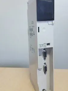
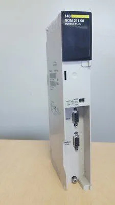
SCHNEIDER 140NOM21100 Electric I/O Module
Negotiable
MOQ: 1 Piece (Price negotiable depending on order volume and customization)
Key Specifications
Get Latest Price
Material:
Other, Global universal model
Condition:
Other, Global universal model
Task:
Other, Global universal model
Payment & Shipping
Payment Methods:
Port of Shipment:
guizhou
Delivery Detail:
Delivery time depends on order quantity.
Related Products
-
 SCHNEIDER 140NRP95400 Fiber Optic Repeater ModuleNegotiableMOQ: 1 Piece
 -
SCHNEIDER 140NRP31200C Ethernet Fiber ModuleNegotiableMOQ: 1 Piece
-
SCHNEIDER 140SDO95300S Digital Output ModuleNegotiableMOQ: 1 Piece
-
SCHNEIDER 140SDI95300S Digital Output ModuleNegotiableMOQ: 1 Piece
-
SCHNEIDER 140XBP01600 Rack BackplaneNegotiableMOQ: 1 Piece
Material
Other, Global universal model
Condition
Other, Global universal model
Task
Other, Global universal model
Mathematical Model
Other, Global universal model
Signal
Other, Global universal model
Customized
Non-Customized
Structure
Other, Global universal model
Operating Temperature
-25℃-70℃
Relative Humidity
5%-95% (non-condensing)
Dimensions
483mm×177mm×120mm
I. Overview
Adopting an industrial-grade bus communication architecture, this module is highly compatible with the backplane bus protocol of the Quantum system, enabling efficient data flow between the control layer and the monitoring layer. It is a key device for building centralized communication networks in medium-to-large industrial automation scenarios.
II. Technical Parameters
III. Functional Features
IV. Working Principle
V. Common Faults and Solutions

Send Inquiry to This Supplier


Business Type
Trading Company
Year Established
2014
Factory Size
1,000-3,000 square meters
Product Certifications
SA8000
You May Also Like
-
SCHNEIDER 140XBP01000 Rack BackplaneNegotiableMOQ: 1 Piece
-
SCHNEIDER 140XBE10000 Backplane ExpanderNegotiableMOQ: 1 Piece
-
SCHNEIDER 140CPU11302 Core Processor ModuleNegotiableMOQ: 1 Piece
-
Schneider 140CPU31110 MODICON QUANTUM Series Unified ProcessorNegotiableMOQ: 1 Piece
-
Schneider 140CPU43412A High-performance Processor ModuleNegotiableMOQ: 1 Piece
-
Schneider 140CPU65260 Control Processor ModuleNegotiableMOQ: 1 Piece
-
Schneider Electric 140CPU67160 Hot Standby CPU ModuleNegotiableMOQ: 1 Piece
-
Schneider 140CPU67160C Modicon Quantum Series Processor ModuleNegotiableMOQ: 1 Piece
-
Schneider Electric 140CPU67260 Multi-mode Processor ModuleNegotiableMOQ: 1 Piece
-
Schneider 140CRA31200 Ethernet IO Station Adapter ModuleNegotiableMOQ: 1 Piece


