

Home > Chemicals > Rubber & Rubber Products > Other Rubber Products > Cost Effective Rubber Inflatable Dam Price for Sale Flood Prevention and Landscape
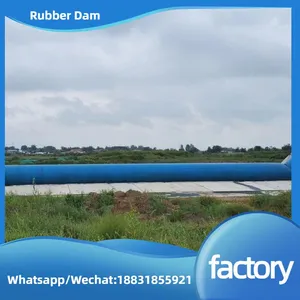
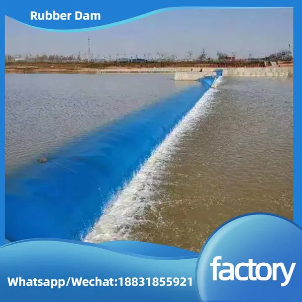
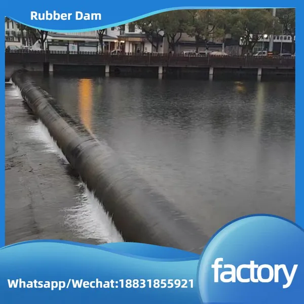
Cost Effective Rubber Inflatable Dam Price for Sale Flood Prevention and Landscape


US$ 300
20 - 49 Meters
US$ 200
50 - 99 Meters
US$ 190
≥100 Meters
Key Specifications
Get Latest Price
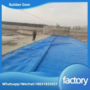
Material:
EPDM
Usage:
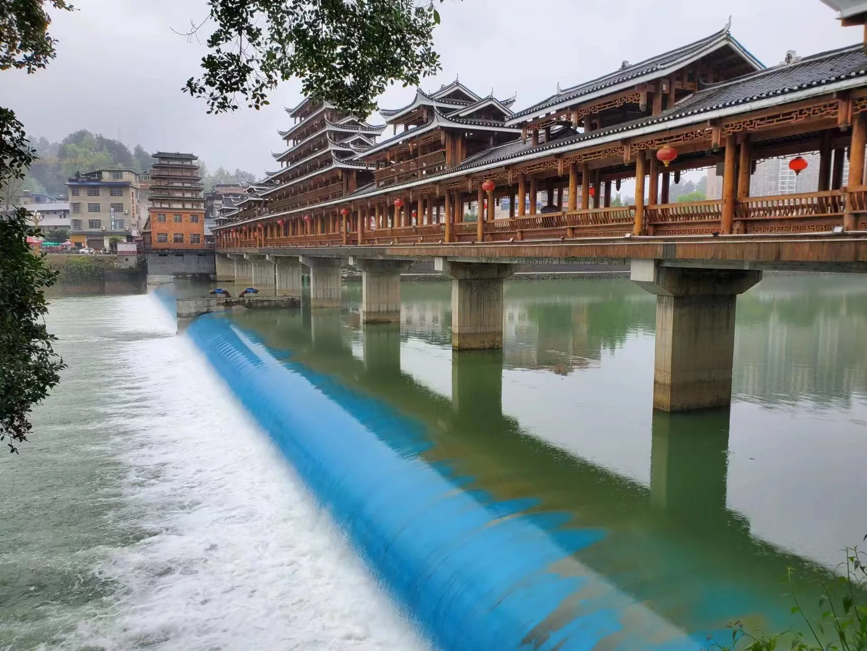
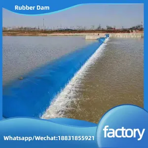
Agricultural, Other, River damming
Transport Package:
Woven bag packaging
Payment & Shipping
Payment Methods:
Port of Shipment:
Tianjin/Qingdao
Delivery Detail:
30 days
Related Products
-
 Factory Price Anti-abrasion Inflatable Rubber Dam With Automatic Control System, Fast Delivery and Technical SupportUS$ 190 - 300MOQ: 20 Meters
 -
Water Filled Rubber Dam Barrier, Inflatable Flexible Membrane Dam for Irrigation and LandscapeUS$ 190 - 300MOQ: 20 Meters
-
Water Inflatable Rubber BladderUS$ 190 - 300MOQ: 20 Meters
-
Inflatable Rubber Dam Weir - Custom Sizes for Efficient Water Control and Flood PreventionUS$ 190 - 300MOQ: 20 Meters
-
Find Similar Icon Anchor Bolt Type Inflatable Rubber Dam With Galvanized Steel Plate for River Water ControlUS$ 190 - 300MOQ: 20 Meters
Material
EPDM
Usage
Agricultural, Other, River damming
Transport Package
Woven bag packaging
Specification
Custom-made according to the drawings
Trademark
HaoGu
Origin
Hebei China
Construction of Rubber Dams: Technical Protocol & Best Practices
1. Pre-Construction Phase: Planning & Preparation
1.1 Site Assessment & Design Validation
1.2 Material Sourcing & Quality Verification
1.3 Equipment & Safety Readiness
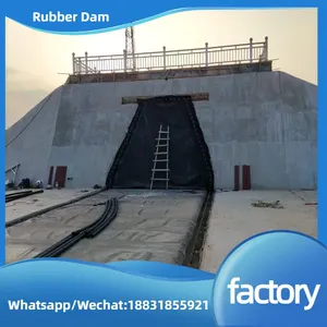
2. Foundation Construction: Building a Stable Base
2.1 Site Clearing & Excavation
2.2 Foundation Reinforcement
2.3 Anchoring System Installation
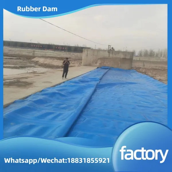
3. Rubber Dam Bag Installation: Precision Handling
3.1 Pre-Installation Preparation
3.2 Dam Bag Unfolding & Alignment
3.3 Anchoring & Sealing
4. Inflation/Deflation System Setup
4.1 Pipeline & Equipment Installation
4.2 System Testing
5. Auxiliary Structures Installation
6. Commissioning & Acceptance
Summary

Send Inquiry to This Supplier

1Yr
Year Established
2025
Factory Size
3,000-5,000 square meters
Annual Export Value
US$5 Million - US$10 Million
Total Employees
51 - 100 People
You May Also Like
-
Find Similar Icon OEM Supplier High Quality Inflatable Rubber Dam, Automatic Water Control System for Irrigation and Flood PreventionUS$ 190 - 300MOQ: 20 Meters
-
Customizable Air Supported Rubber Dam / Inflatable Barrage, Automatic Water Control System for Irrigation and LandscapeUS$ 190 - 300MOQ: 20 Meters
-
Customizable Air Supported Rubber DamUS$ 190 - 300MOQ: 20 Meters
-
Water Conservancy Project Air Inflatable Rubber River Water Dam/Rubber Dam/Air Shield Dam/Foundation/Dam BagUS$ 190 - 300MOQ: 20 Meters
-
Rubber Dam, Smooth Surface, Made of Rubber Black Fin Form, Effective to Reduce VibrationUS$ 190 - 300MOQ: 20 Meters
-
Rubber Dam, Made of High-strength Synthetic Fabrics, Supported by a Frame, and Prefabricated RubberUS$ 190 - 300MOQ: 20 Meters
-
Air Inflatable Rubber Dam, Air Filling Rubber DamUS$ 190 - 300MOQ: 20 Meters
-
Fin Rubber Dam, OEM Services Are Provided, Made of Rubber Material, ISO:9001 MarksUS$ 190 - 300MOQ: 20 Meters
-
High-Performance Inflatable Rubber Dam for Flood Control, Fast Inflation & Deflation Emergency Water Barrier With UV ResistanceUS$ 290 - 300MOQ: 20 Meters
-
Eco-Friendly Inflatable Rubber Dam for Dry-Season Water Storage, Adjustable Height & Lightweight Design Easy InstallationUS$ 190 - 300MOQ: 20 Meters


