



Home > Electrical & Electronics > Electrical Control System > SCHNEIDER 140CHS11100 Hot Standby I/O Module
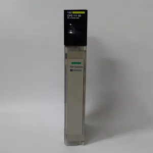
SCHNEIDER 140CHS11100 Hot Standby I/O Module
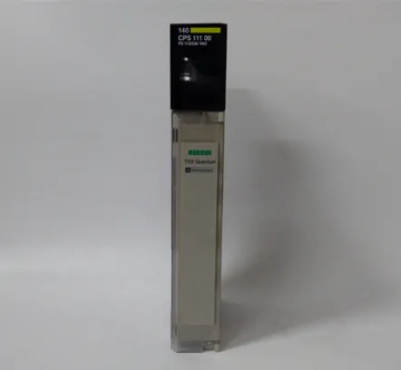
SCHNEIDER 140CHS11100 Hot Standby I/O Module photo-1

Negotiable MOQ: 1 Piece (Price negotiable depending on order volume and customization)
Key Specifications
Get Latest Price
Material:
Other, Global universal model
Condition:
Other, Global universal model
Task:
Other, Global universal model
Payment & Shipping
Payment Methods:
Port of Shipment:
guizhou
Delivery Detail:
Delivery time depends on order quantity.
Material Other, Global universal model
Condition Other, Global universal model
Task Other, Global universal model
Mathematical Model Other, Global universal model
Signal Other, Global universal model
Customized Non-Customized
Structure Other, Global universal model
Operating Temperature 0℃-60℃
Relative Humidity 5%-95% (non-condensing)
Dimensions 100mm×160mm×220mm

I. Overview


Schneider 140CHS11100 is a core backplane bus expansion module for the Modicon Quantum series Programmable Logic Controllers (PLCs). Its core positioning is a "bus expansion and signal relay unit for medium and large-sized industrial control systems", focusing on solving system expansion challenges in complex industrial scenarios such as metallurgy, chemical engineering, electric power, and intelligent manufacturing. These challenges arise from insufficient controller I/O interfaces, excessive control distances, or signal transmission attenuation.


This module is highly compatible with the bus architecture of Modicon Quantum series PLCs. It adopts industrial-grade bus drive circuits, signal relay amplification technology, and redundant design. Its key functions include expanding the number of system I/O slots, extending bus transmission distance, enhancing bus signal strength, and ensuring the stability of multi-module collaborative communication. It provides core bus support for the modular expansion, distributed deployment, and reliable operation of medium and large-sized industrial control systems.


As a main bus expansion module in the Modicon Quantum series, the 140CHS11100 has core advantages such as a 10-slot standard configuration, bus signal relay amplification, hot-swap compatibility, and industrial-grade stability. It enables flexible expansion of control systems without additional bus expansion adapters, effectively improving system scalability and deployment flexibility.


It is widely used in various medium and large-sized industrial automation control systems, such as blast furnace cluster control in the metallurgical industry, distributed control of multiple reactors in the chemical industry, auxiliary control systems for generator sets in the electric power industry, and distributed I/O expansion for large production lines in the intelligent manufacturing field. The module features seamless compatibility with the Modicon Quantum system, 10-slot expansion capability, bus signal enhancement, industrial-grade anti-interference, and fault self-diagnosis. It can adapt to harsh industrial environments such as high temperature, high humidity, and strong electromagnetic interference, fully meeting the high requirements of medium and large-sized industrial control systems for bus expansion accuracy, real-time performance, and stability.


II. Technical Specifications


Parameter Category Specific Specifications Detailed Description
Core Expansion & Adaptation Parameters Adaptation Platform Specifically designed for Schneider Modicon Quantum series PLCs; compatible with Quantum series standard backplane bus protocols; supports collaborative work with all controllers of the Quantum series (e.g., 140CPU67160) and Unity Pro programming software

Slot Configuration 10 standard I/O module slots; supports insertion of Quantum series digital, analog, and special function modules; synchronous bus signal transmission between slots; supports mixed module insertion (different types of I/O modules can be combined arbitrarily)

Bus Expansion Capability A single module can expand 10 I/O slots; supports multi-module cascading expansion (maximum 3 cascading levels); each cascading level can extend the bus transmission distance by 10 meters; the total number of expanded slots depends on the controller model (maximum 60 expanded slots supported)

Bus Performance Bus communication rate: 1Mbps (synchronized with the main controller); signal transmission delay: ≤1μs/slot; bus load capacity: supports simultaneous operation of 10 fully loaded I/O modules; supports bus signal relay amplification function, with signal attenuation ≤5% after cascading


Interface & Connection Parameters

Bus Interface


Equipped with 2 standard Quantum bus interfaces (1 input, 1 output); interface type: European-style pin connector; bus connection method: bolt-fastened; supports bus redundant connection (requires matching redundant modules)


Power Interface Adopts dual-power input interface; interface type: screw-type terminal block; input voltage: DC 5V ±5% (obtained from the main backplane or dedicated power module); supports redundant power input (automatic dual-power switching)

Diagnostic Interface Supports communication with the main controller via the backplane bus to upload module status information; equipped with 2 status indicators (BUS for bus communication, PWR for power); supports real-time display of fault information via Unity Pro software


Power Supply & Power Consumption Parameters


Power Supply Specifications


Rated power supply voltage: DC 5V ±5%; input current: ≤2A (no-load), ≤5A (10 fully loaded I/O modules); equipped with over-voltage protection (triggered at 120% of rated voltage) and over-current protection (triggered at 6A)


Power Consumption Indicators No-load power consumption: ≤3W; full-load power consumption: ≤12W (with 10 standard I/O modules connected); standby power consumption: ≤1.5W
Environmental & Physical Parameters Environmental Parameters


Operating temperature: 0℃-60℃; storage temperature: -40℃-85℃; relative humidity: 5%-95% (no condensation); vibration resistance: 10-500Hz, 1g (three axes); shock resistance: 15g (peak, 11ms, three axes); electromagnetic compatibility: compliant with EN 61000-4-2/3/4/5/6 standards


Physical & Installation Parameters Dimension specifications: 100mm×160mm×220mm (length×width×height); installation method: embedded installation in Modicon Quantum standard rack; weight: approximately 1.5kg; housing material: cold-rolled steel plate (with anti-corrosion coating); protection level: IP20 (panel)


Reliability & Management Parameters


Reliability Indicators


Mean Time Between Failures (MTBF): ≥200,000 hours; bus signal anti-interference capability: common-mode rejection ratio ≥80dB, differential-mode rejection ratio ≥60dB; service life: ≥10 years (under normal working environment)


Configuration Management Supports automatic identification by Unity Pro software; no separate parameter configuration required (parameters synchronized with the main controller); supports online monitoring of module working status (bus rate, power voltage, slot occupancy); supports fault log query and export

140CHS11100


III. Functional Features


1. Deep Compatibility with Modicon Quantum System for Efficient and Convenient Expansion Deployment

It adopts a bus adaptation architecture specially developed for the Modicon Quantum series, achieving full-dimensional deep compatibility with the system's main controller, other I/O modules, and software platforms, significantly improving expansion deployment efficiency and operational stability.
The module can be directly embedded in a Quantum standard rack and quickly connected to the main backplane or previous-stage expansion module via a dedicated bus interface, without the need for additional bus drive software or configuration tools. Physical installation only requires three steps: rack fixing, bus connection, and power access, reducing installation time by 50% compared to traditional expansion modules.
After being connected to the system, the main controller can automatically identify the module model, number of slots, and information of connected I/O modules via the bus, eliminating the need for engineers to manually add devices. The real-time status of the expansion module and the working information of modules in each slot can be directly displayed in Unity Pro software, simplifying the system management process.
It supports collaborative work with Quantum series hot-swap modules. In line with the system's hot-swap specifications, I/O modules in the expansion slots can be replaced without shutting down the unit, realizing "zero-downtime" maintenance. This makes it particularly suitable for critical industrial control scenarios such as chemical engineering and electric power.


2. Flexible 10-Slot Expansion for Adapting to Diverse Control Requirements

With a 10-slot standard configuration design, it balances the needs for high-density expansion and flexible configuration, and can adapt to industrial control scenarios of different complexities.
The 10 slots support insertion of various Quantum series I/O modules, including digital input/output modules, analog input/output modules, pulse modules, and communication modules. Engineers can arbitrarily combine module types and quantities according to control requirements. For example, in the expansion of an intelligent manufacturing production line, 3 digital input modules, 3 digital output modules, 2 analog input modules, and 2 analog output modules can be configured to achieve comprehensive collection and control of various signals in the production line.
It supports multi-module cascading expansion, with a maximum of 3 cascading levels. Each level provides 10 slots. Combined with the slots of the main controller itself, it can achieve expansion of up to 60 I/O slots, meeting the multi-point control needs of large industrial control systems.
The slots adopt a standardized design, enabling smooth module insertion and removal, and are equipped with an anti-misinsertion structure. This effectively prevents equipment damage caused by incorrect module insertion and improves the safety of expansion configuration.


3. Bus Signal Relay Amplification for Stable and Reliable Transmission

Equipped with an industrial-grade bus signal relay amplification circuit, it effectively solves the problem of signal attenuation in long-distance bus transmission and ensures the communication stability of the expansion system.
The module is provided with dual bus interfaces (input and output). The input interface receives bus signals from the main backplane or previous-stage module. After processing by the internal relay amplification circuit, the signals are transmitted to the next-stage module or I/O module via the output interface. The signal amplification gain can be automatically adjusted according to the transmission distance. Even after 3 cascading levels, the signal attenuation is still ≤5%, which is much lower than the industry average attenuation level (15%).
The bus communication rate is synchronized with the main controller, reaching 1Mbps, and the signal transmission delay is ≤1μs/slot. This ensures that the I/O signals connected to the expansion module can be uploaded to the main controller in real time, and the control commands from the main controller can also be issued to each execution module in real time, meeting the high real-time requirements of industrial control.
It adopts a bus signal isolation design. The internal bus circuit of the module is electrically isolated from the power circuit and slot circuit, with an isolation voltage of 2000VAC. This can effectively resist the impact of external electromagnetic interference on bus signals and ensure stable communication even near strong interference sources such as frequency converters and motors.


4. Industrial-Grade Anti-Interference and Protection for Adapting to Harsh Environments

With multiple industrial-grade anti-interference and protection designs, it has excellent environmental adaptability and can work stably in the harsh operating environment of industrial sites.
The module internally adopts a triple isolation architecture of "bus signal isolation + power isolation + slot signal isolation". The isolation voltage between the bus and power supply, and between the bus and slots is 2000VAC, which can effectively resist external high-voltage shocks, surges, and signal crosstalk.
The internal circuit adopts an enhanced EMC (Electromagnetic Compatibility) design. Through technologies such as filter circuits, metal shields, and grounding optimization, it complies with EN 61000-4-2/3/4/5/6 standards and can work normally in strong electromagnetic interference environments, with a bus communication bit error rate ≤10⁻⁹.
The housing is made of cold-rolled steel plate with an anti-corrosion coating, featuring good vibration resistance, shock resistance, and corrosion resistance. It has a vibration resistance rating of 10-500Hz, 1g and a shock resistance rating of 15g, which can adapt to high-vibration and dusty environments in metallurgical workshops.
The operating temperature range covers 0℃-60℃, and it adopts a natural heat dissipation design without the need for cooling fans, enabling stable operation in high-temperature steel mill workshops or cold outdoor control cabinets.
At the same time, the module is equipped with over-voltage and over-current protection functions. When the input voltage or current exceeds the rated range, the protection circuit is quickly triggered to cut off the power supply of some non-core circuits, avoiding module damage.


5. Dual-Power Redundant Input for Safe and Reliable Power Supply

Adopting a dual-power redundant input design, it significantly improves the reliability of module power supply and avoids the paralysis of the expansion system caused by a single power failure.
The module is equipped with two independent power input interfaces, which can be connected to two independent DC 5V power supplies (such as the main backplane power supply and a dedicated backup power supply). During normal operation, the two power supplies supply power simultaneously, with balanced load distribution.
When one of the power supplies fails (such as power failure, over-voltage, or over-current), the power switching circuit inside the module can automatically switch to the other power supply for power supply within 1ms. During the switching process, bus communication and slot power supply are not interrupted, ensuring the continuous operation of the expansion system.
The power input circuit adopts a high-precision voltage detection chip, which can real-time monitor the voltage status of the two power supplies and upload the power status information to the main controller via the bus. Engineers can real-time check the power working status through Unity Pro software and provide early warning of power failures.
The power interface adopts a screw-type terminal block design, ensuring firm wiring and low contact resistance, which can effectively avoid power supply instability caused by loose wiring.


6. Full-Dimensional Status Monitoring for Significantly Improved Operation and Maintenance Efficiency

It integrates full-dimensional status monitoring functions at the module level, bus level, and slot level, which can real-time feed back equipment operating status and quickly locate faults, significantly reducing operation and maintenance costs.
The module is equipped with two status indicators: BUS (bus communication) and PWR (power). The working status of the module is intuitively fed back through the on/off and blinking states of the indicators: the BUS indicator stays on when bus communication is normal, blinks when communication is abnormal, and is off when the bus is not connected; the PWR indicator stays on when dual-power supply is normal, is half-on when only one power supply is working, and is off when there is no power input.
The module transmits detailed status information (including power voltage, bus rate, slot occupancy, fault type, etc.) to the main controller via the bus. Engineers can real-time view various parameters and historical operating data of the expansion module through Unity Pro software, which supports fault log storage (capable of storing 100 fault records) and export analysis.
When bus communication abnormalities, power failures, or slot module failures occur, the software can quickly locate the fault location and issue an alarm prompt. There is no need for engineers to check each module one by one, reducing fault troubleshooting time by more than 80%.


IV. Common Faults and Solutions


Fault Phenomenon Possible Causes Solutions Precautions
Module cannot be recognized by the system, and the BUS indicator is off 1. Bus interface not connected or loosely connected; 2. Module not fully inserted into the rack, resulting in poor contact; 3. Incompatibility between the main controller's firmware version and the module; 4. Damaged bus interface or faulty bus cable; 5. Module power not connected or abnormal power supply
  1. After power-off, check the bus interface connection, reinsert the bus cable, and fasten the bolts; 2. Turn off the system power, reinsert the module to ensure it is tightly clamped, and clean the dust in the rack slots; 3. Refer to the Schneider compatibility manual and upgrade the main controller's firmware to a compatible version via Unity Pro; 4. Replace the bus cable for testing; if the problem persists, check the module's bus interface and contact after-sales service if the fault is confirmed; 5. Use a multimeter to measure the power input voltage to ensure it is DC 5V ±5%, and reconnect the power line


Power must be turned off before inserting/removing the module and bus cable to avoid damaging the interface; system configuration and programs must be backed up before firmware upgrade; a high-precision multimeter must be used when measuring power voltage
BUS indicator blinks, and bus communication is abnormal 1. Excessive bus signal attenuation (more than 3 cascading levels or excessive transmission distance); 2. Presence of strong electromagnetic interference sources nearby; 3. Overloaded bus (number of connected modules exceeds the rated value); 4. Poor contact or oxidation of the bus interface; 5. Faulty bus port of the main controller
  1. Reduce the number of cascading levels (control within 3 levels), shorten the bus transmission distance, or add a bus relay module; 2. Keep the module away from interference sources such as frequency converters and motors, or install a metal shield; 3. Reduce the number of connected I/O modules to ensure no more than 10 fully loaded modules; 4. After power-off, clean the oxide layer on the bus interface pins, reconnect, and fasten; 5. Connect the module to other bus ports of the main controller for testing; if the fault is confirmed, repair the main controller


The bus transmission distance per level is recommended to be no more than 10 meters; the shield must be reliably grounded; a 20% margin should be reserved for the bus load to avoid full-load operation
PWR indicator is half-on, and one power supply fails 1. Loose or broken wiring of the faulty power line; 2. Damaged faulty power module (e.g., abnormal output voltage); 3. Damaged module power input interface; 4. Faulty power switching circuit 1. After power-off, check the faulty power line, re-fasten the wiring or replace the broken cable; 2. Use a multimeter to measure the output voltage of the faulty power module; replace the power module if it is confirmed damaged; 3. Connect the faulty power supply to other expansion modules for testing; if the problem persists, it indicates a module interface fault, and contact after-sales service for repair; 4. Restart the module and observe the status of the PWR indicator; if it remains half-on, the switching circuit is faulty and requires repair by professionals When replacing the power module, an industrial-grade power module of the same model must be used; mark the wiring sequence when checking the lines to avoid wrong connection; the repair of the power switching circuit must be performed by Schneider-certified engineers
Product Tags: 140CHS11100

Send Inquiry to This Supplier

* Message
0/5000

Want the best price? Post an RFQ now!
Verified Business License
Business Type
Trading Company
Year Established
2014
Factory Size
1,000-3,000 square meters
Product Certifications
SA8000

