

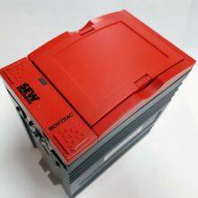
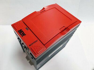
SEW 31C005-503-4-00 Servo Controller
Related Products
-
 SEW 31C075-503-4-00 Servo ControllerNegotiableMOQ: 1 Piece
 -
SEW 31C015-503-4-00 Servo ControllerNegotiableMOQ: 1 Piece
-
SEW 31C450-503-4-00 Servo ControllerNegotiableMOQ: 1 Piece
-
SEW 31C055-503-4-00 Servo ControllerNegotiableMOQ: 1 Piece
-
PIONEER MAGNETICS PM1253AL-6-3-Z03 Power ModuleNegotiableMOQ: 1 Piece
I. Overview
The SEW 31C005-503-4-00 is a servo drive, with its core positioning as a "cost-effective motion control unit" for small automated equipment, light-load conveyor systems, small packaging machinery, and household automation upgrades. Inheriting SEW's mature technical accumulation in the drive field, this drive adopts a simplified vector control algorithm, a highly integrated hardware architecture, and a cost-optimized design. It undertakes key tasks such as precise speed regulation of low-power servo motors, basic position control, stable torque output, and data interaction with simple upper-level control systems. Meanwhile, it features good compatibility with SEW small servo motors, economical PLCs, and general human-machine interaction devices, ensuring the reliability, economy, and convenience of motion control in light-load and miniaturized drive scenarios.
As the main economical model of the 31C series, the 31C005-503-4-00 is highly compatible with SEW CMP series small servo motors (e.g., CMP71M4), HCS10 simple operation panels, and conventional incremental encoders. It can be flexibly integrated into small automated systems through mainstream methods such as pulse control and analog control, and can complete core operations including control mode switching, basic parameter calibration, and fault diagnosis without complex configurations. It is widely used in key fields such as roller drive for small conveyor lines, sealing and cutting mechanism drive for small packaging machinery, actuator drive for household automation equipment, and motion drive for light-load sorting equipment. It provides core drive support for the light torque output, basic positioning, and stable operation of equipment, and is a key component for reducing the cost of small automated equipment, improving the operational stability of equipment, and simplifying the operation and maintenance process. The drive has core characteristics including simplified vector control, multi-control mode adaptation, basic safety protection, high cost-effectiveness, and convenient operation and maintenance. It can adapt to operating conditions such as conventional electromagnetic interference, small voltage fluctuations, and light-load impacts in small industrial sites, fully meeting the usage requirements of miniaturized and low-cost drive scenarios.
II. Technical Parameters
III. Functional Features
1. Simplified Vector Control for Small Light-Load Scenarios
2. Practical Interface Configuration for Convenient Small-System Integration
3. Basic Safety Protection for Stable and Reliable Operation
4. Cost-Effective Design for Precise Cost Control
5. Miniaturized & Convenient Operation and Maintenance for Reduced Management Costs
6. Basic Environmental Adaptability for Small-Scenario Requirements
It adopts a basic anti-interference and environment-adaptive design, fully meeting the operating needs of small industrial scenarios and household automation upgrades. The power input side is equipped with a basic EMC filter, complying with the EN 61800-3 EMC basic level standard, which can effectively suppress common power grid interference and avoid interference to other electronic components of small equipment. The control signals adopt photoelectric isolation protection, and in ordinary industrial environments (e.g., small workshops, packaging workshops), the signal transmission error rate is ≤0.001%, ensuring stable transmission of control signals. It has a wide voltage input range (380-480VAC±10%), which can adapt to areas or small workshop scenarios with small power grid voltage fluctuations without additional voltage regulators. The operating temperature range supports 0℃-50℃, and the natural heat dissipation design does not require additional cooling equipment, adapting to the installation environment of small equipment without forced heat dissipation. The relative humidity is 10%-90% (non-condensing), and the protection class reaches IP20, meeting the basic protection needs of cabinet-mounted installation of small equipment.
IV. Common Faults and Solutions

Send Inquiry to This Supplier


You May Also Like
-
PIONEER MAGNETICS PM3328B-6-1-3-E Power ModuleNegotiableMOQ: 1 Piece
-
PIONEER MAGNETICS PM3398BP-6-1-3-E Power ModuleNegotiableMOQ: 1 Piece
-
NDELAG INFO-4KP-94161D Signal Conversion ModuleNegotiableMOQ: 1 Piece
-
MAGNETEK HP4-1D-T-S1139 Power SupplyNegotiableMOQ: 1 Piece
-
Molex SST-SR4-CLX-RLL Serial Communication ModuleNegotiableMOQ: 1 Piece
-
METASYS NU-NCM350-8 Network Control ModuleNegotiableMOQ: 1 Piece
-
MILLIPORE CMHT-11S02 Filtration ModuleNegotiableMOQ: 1 Piece
-
MITSUBISHI QM100DY-H Digital I/O ModuleNegotiableMOQ: 1 Piece
-
MITSUBISHI QM100HY-H Digital I/O ModuleNegotiableMOQ: 1 Piece
-
KUKA KK67Y-YYYY-050 Control SystemNegotiableMOQ: 1 Piece


