

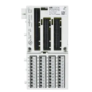
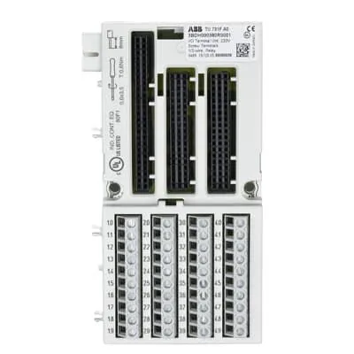
ABB TU731F 3BDH000380R0001 I/O Terminal Unit, 230 VAC
Related Products
-
 ABB AI810 3BSE008516R1 Analog Input 8 chNegotiableMOQ: 1 Piece
 -
ABB AI820 3BSE008544R1 Analog Input 4 chNegotiableMOQ: 1 Piece
-
ABB AI815 3BSE052604R1 Analog Input HART 8 chNegotiableMOQ: 1 Piece
-
ABB AO820 3BSE008546R1 Analog Output 4 chNegotiableMOQ: 1 Piece
-
ABB AO895 3BSC690087R1 Analog Output IS HART 8 chNegotiableMOQ: 1 Piece
I. Overview
ABB TU731F 3BDH000380R0001 is a high-performance IO module interface base, a key hardware support component of the AC 800M series distributed control system. It is specifically designed to meet the requirements of IO module integration, multi-type on-site signal conversion, and high-reliability power distribution in medium and large-scale industrial process control scenarios. Adopting a compact modular architecture and precision contact connection technology, this base integrates core functions such as multi-type signal adaptation, dual redundant power supply, accurate mechanical positioning, and enhanced electromagnetic compatibility protection. It provides stable mechanical support, efficient signal transmission links, and comprehensive safety protection for full-specification IO modules of the AC 800M series (e.g., AI890 analog input module, DI810 digital input module, AO890 analog output module, etc.).
II. Functional Features
ABB TU731F 3BDH000380R0001 is highly compatible with the high reliability and high expandability design requirements of the AC 800M series control system. Integrating ABB's core technologies in the field of industrial connection and signal processing, it has the following core functional features:
III. Technical Parameters
IV. Working Principle
As a core interface unit of the AC 800M series IO modules, the working principle of ABB TU731F 3BDH000380R0001 revolves around four core links: "intelligent power distribution - multi-type signal conversion - full status monitoring - dual redundancy protection", realizing efficient collaboration and safe operation between IO modules and various units of the system. The specific working principle is as follows:

Send Inquiry to This Supplier


You May Also Like
-
ABB AO845 3BSE023676R1 Analog Output ModuleNegotiableMOQ: 1 Piece
-
ABB AO650 3BHT300051R1 Analog Output 8ch, 12bit Chan IsolNegotiableMOQ: 1 Piece
-
ABB AO890 3BSC690072R1 Analog Output IS 8 chNegotiableMOQ: 1 Piece
-
ABB SB821 3BSE018109R1 Battery UnitNegotiableMOQ: 1 Piece
-
ABB SS822 3BSC610042R1 Voting DeviceNegotiableMOQ: 1 Piece
-
ABB SS832 3BSC610068R1 Power Voting UnitNegotiableMOQ: 1 Piece
-
ABB PL810 3BDH000311R0101 Programmable Controller ModuleNegotiableMOQ: 1 Piece
-
ABB PL890 3BDH003115R0101 Programmable Controller ModuleNegotiableMOQ: 1 Piece
-
ABB DO810 3BSE008510R1 Digital Output 24V 16 chNegotiableMOQ: 1 Piece
-
ABB DO890 3BSC690074R1 Digital Output IS 4 chNegotiableMOQ: 1 Piece


