



Home > Electrical & Electronics > Electrical Control System > ABB AO845 3BSE023676R1 Analog Output Module
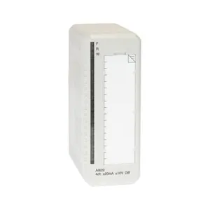
ABB AO845 3BSE023676R1 Analog Output Module
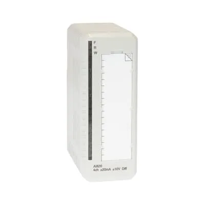
ABB AO845 3BSE023676R1 Analog Output Module photo-1

Negotiable MOQ: 1 Piece (Price negotiable depending on order volume and customization)
Key Specifications
Get Latest Price
Material:
Other, Global universal model
Condition:
Other, Global universal model
Task:
Other, Global universal model
Payment & Shipping
Payment Methods:
Port of Shipment:
guizhou
Delivery Detail:
Delivery time depends on order quantity.
Material Other, Global universal model
Condition Other, Global universal model
Task Other, Global universal model
Mathematical Model Other, Global universal model
Signal Other, Global universal model
Customized Non-Customized
Structure Other, Global universal model
Operating Temperature -20℃ to 60℃
Relative Humidity 5%-95% (non-condensing)
Dimensions 100×160×80mm

I. Product Overview


ABB AO845 3BSE023676R1 is a key analog output module in the AC 800M series distributed control system. Specifically designed for actuator driving and process parameter adjustment in industrial process control scenarios, it is widely used in critical control loops across industries such as electric power, petrochemicals, metallurgy, water treatment, and papermaking. As a core signal conversion unit between the system and on-site actuators, this module undertakes the core function of converting the digital control signals output by the controller into high-precision analog signals. It can directly drive actuators like control valves, frequency converters, and servo motors, enabling precise closed-loop control of critical process parameters such as temperature, pressure, flow rate, and liquid level.


Based on the unified modular and redundant architecture design of the AC 800M system, this module is compatible with main controllers of the PM864, PM865, and other series. It supports hot-swap replacement and dual-module redundant configuration, allowing maintenance and upgrades to be completed without shutting down the system, thus significantly improving the continuity and reliability of control loops. It features industrial-grade anti-interference capability and wide environmental adaptability, having passed the IEC 61000 series electromagnetic compatibility certification and EN 61010-1 safety certification. It can operate stably in industrial on-site environments with high temperature, high humidity, and strong electromagnetic interference, serving as a core component to ensure precise control and safe operation of industrial processes.


II. Functional Features


  • Multi-Channel High-Precision Analog Output: The module integrates 8 independent analog output channels. Each channel can be flexibly configured with output types via software, supporting three common analog signal types: 4-20mA DC current output, 0-20mA DC current output, and 0-10V DC voltage output, to meet the signal requirements of different actuators. Equipped with a 16-bit high-precision D/A converter, it achieves an output accuracy of ±0.1%FS and a linearity error of ≤0.05%FS, enabling fine adjustment of actuators. Each channel supports custom calibration of the output range to adapt to actuators with special range requirements, and the channels are isolated from each other with an isolation voltage of 250V DC, effectively preventing inter-channel interference.


  • Multi-Level Signal Optimization and Anti-Interference Design: It adopts a three-level anti-interference architecture of "Digital Isolation - Signal Amplification - Output Filtering". The module integrates a high-speed photoelectric isolation chip internally to achieve electrical isolation between the digital control loop and the analog output loop, with an isolation voltage of 250V DC, effectively suppressing common-mode interference and differential-mode interference. Each channel has a built-in programmable gain amplifier and low-pass filter network, and the filter cutoff frequency can be set via software (adjustable from 1Hz to 100Hz), which can accurately filter high-frequency electromagnetic noise in industrial sites. The power input terminal of the module is equipped with an EMC filter circuit, complying with the IEC 61000-4-2/3/4/5 electromagnetic compatibility standards, and can withstand ±2kV electrostatic discharge, ±1kV surge impact, and electromagnetic radiation interference of over 80dB.


  • Flexible Redundant Configuration and Hot-Swap Capability: It supports the 1:1 redundant configuration mode of the AC 800M system. Two AO820 modules can be formed into a redundant output pair, and data synchronization between the master and slave modules is realized through the system backplane bus, with a synchronization delay of ≤1ms. When the master module fails, the slave module can seamlessly take over the output task, and the switching time of the output signal is ≤50μs, ensuring no interruption of the control loop. Adopting a standardized guide rail mounting structure and hot-swap design, it supports live hot-swap operations. The built-in contact protection circuit during plugging and unplugging can prevent arc generation, avoiding damage to the module and associated equipment. The hot-swap replacement time is ≤60 seconds, greatly shortening maintenance downtime.


  • Comprehensive Fault Diagnosis and Alarm Mechanism: It has a built-in high-precision fault detection circuit that monitors fault types in real time, such as module power failure, D/A converter failure, channel short circuit, output overload, and cable open circuit. When a fault is detected, the module immediately feeds back the fault status through LED indicators (independent indicator for each channel) and uploads the fault code and fault location information to the main controller and upper monitoring system via the system bus. It supports the fault-safe output function, allowing presetting of safe output values (such as 4mA, 20mA, or custom values) in case of faults, to prevent dangerous actions of the actuator in the fault state and ensure the safety of the production process.


  • Convenient Calibration and Maintenance Functions: It supports two calibration modes: automatic calibration and manual calibration. The automatic calibration process can be initiated through the ABB Control Builder M configuration software. The built-in calibration circuit of the module will automatically correct the zero and gain errors of the D/A converter, and no module disassembly or external calibration equipment is required during the calibration process. In the manual calibration mode, calibration points (zero point and full-scale point) can be set via software, and high-precision calibration can be completed with a standard calibrator. The module has a built-in non-volatile memory that can store calibration data and configuration parameters, which will not be lost when the power is off. Parameters can be quickly imported when replacing the module, improving maintenance efficiency.


  • Efficient System Integration and Configuration Capability: It is perfectly compatible with the ABB AC 800M control system and realizes high-speed data interaction with the main controller through PROFIBUS DP or Ethernet/IP fieldbus, with a maximum communication rate of 12Mbps. It supports ABB standard configuration languages such as Function Block Diagram (FBD) and Structured Text (ST). Through the Control Builder M software, visual configuration of parameters such as channel output type, range, filter parameters, and fault-safe values can be realized. It is compatible with third-party SCADA systems (such as ABB OPC Server, WinCC, iFIX) and supports remote monitoring of module status and output parameters through the OPC protocol.


3BSE008544R1


III. Technical Parameters


Parameter Category Parameter Name Specific Parameters Unit
Basic Parameters Model ABB AO845 3BSE023676R1 -

Product Type Analog Output Module -

Overall Dimensions (L×W×H) 100×160×80 mm

Weight Approximately 0.65 kg


Output Performance Parameters


Number of Channels


8 channels, independent isolation

Channel

Output Signal Type 4-20mA DC, 0-20mA DC, 0-10V DC (software selectable) -

D/A Converter Precision 16-bit Bit

Output Accuracy ±0.1%FS (25℃±5℃); ±0.2%FS (0℃-55℃) -

Linearity Error ≤0.05%FS -

Response Time ≤1ms (from digital signal input to stable analog signal output) ms


Electrical Performance Parameters


Inter-Channel Isolation Voltage


250V DC

V DC

Power-Signal Isolation Voltage 250V DC V DC

Load Capacity Current output: ≤500Ω; Voltage output: ≥10kΩ Ω/kΩ

Filter Cutoff Frequency 1Hz-100Hz, software adjustable Hz


Power and Communication Parameters

Power Supply Voltage DC 24V±10%, supporting redundant power supply V DC

Operating Current ≤80mA at no load; ≤200mA at full load mA

Communication Interface PROFIBUS DP, Ethernet/IP (via system backplane bus) -

Communication Rate Up to 12Mbps Mbps


Environmental and Reliability Parameters

Operating Temperature Range -20~60

Storage Temperature Range -40~85

Relative Humidity 5%-95% (no condensation) %

Protection Level IP20 (panel) -

Mean Time Between Failures (MTBF) ≥300,000 Hour


IV. Working Principle


The working principle of the ABB AO845 3BSE023676R1 analog output module revolves around the core link of "Data Reception - Signal Conversion - Output Driving - Fault Monitoring - Data Feedback", combined with a redundancy guarantee mechanism to achieve high-precision conversion and reliable output from digital control signals to analog output signals. The specific process is as follows:


  1. Redundant Power Supply and System Initialization:The module is connected to a DC 24V redundant power supply. After rectification, filtering, and voltage stabilization through the built-in power management circuit, a stable DC voltage is output to power the internal CPU, D/A conversion circuit, isolation circuit, driving circuit, and other units of the module. The power management circuit monitors the status of the two input power supplies in real time. When one power supply fails (voltage lower than 21.6V or higher than 26.4V), it immediately switches to the other power supply, with a switching time of ≤1ms to ensure continuous operation of the module. After the module is powered on, it establishes communication with the main controller through the system backplane bus, executes the initialization program, and self-checks the status of the CPU, D/A converter, communication interface, and channel circuit. After initialization, it uploads its own status information (ready/fault) to the main controller and feeds back the operating status through the front-end LED indicators.

  2. Control Data Reception and Parsing:The main controller transmits the digital control commands (such as valve opening commands) calculated by the control algorithm to the module through the PROFIBUS DP or Ethernet/IP bus. After the module's communication interface receives the data, it is isolated by the digital isolation circuit and sent to the internal CPU for parsing. Based on the preset configuration parameters (channel output type, range, etc.), the CPU converts the digital commands into D/A conversion reference values for the corresponding channels, and assigns independent conversion tasks to each channel to avoid inter-channel interference.

  3. D/A Conversion and Signal Conditioning:The CPU sends the parsed digital reference values to the 16-bit D/A converters of the corresponding channels respectively. The D/A converters convert the digital signals into analog current or voltage signals (according to the configured output type). The converted analog signals are sent to the programmable gain amplifier, and the signal amplitude is adjusted according to the range requirements to ensure the output signal meets the set range (such as 4-20mA). Then the signals enter the low-pass filter network to filter high-frequency electromagnetic noise, and the filter cutoff frequency can be set via software (adjustable from 1Hz to 100Hz) according to the on-site interference situation. The conditioned analog signals are isolated by the photoelectric isolator to achieve electrical isolation between the digital loop and the analog output loop, with an isolation voltage of 250V DC, effectively suppressing common-mode interference.

  4. Analog Output and Driving:The isolated analog signals are sent to the power driving circuit. The power driving circuit provides sufficient driving capability according to the signal type (current/voltage) to drive the actuator (such as a control valve, frequency converter) to act. In the current output mode, the driving circuit adopts a constant current source design to ensure stable output current. When the load resistance changes within the range of 0-500Ω, the output current accuracy remains ±0.1%FS. In the voltage output mode, a voltage follower design is adopted to ensure stable output voltage. When the load resistance is ≥10kΩ, the output voltage accuracy meets the requirements. The module collects the actual output value of each channel in real time and feeds it back to the CPU for closed-loop calibration. If the deviation between the actual output value and the theoretical value exceeds the threshold, the CPU automatically adjusts the D/A conversion reference value to ensure output accuracy.

  5. Fault Monitoring and Safety Handling:The module has a built-in comprehensive fault detection circuit that monitors the following fault types in real time: abnormal power supply voltage (too high/too low), D/A converter conversion error, channel output short circuit (load resistance

  6. Redundancy Switching and Data Feedback:In the redundant configuration mode, the master and slave AO820 modules synchronize configuration parameters and output commands in real time through the system backplane bus, and the master module sends its own operating status (output value, fault status) to the slave module in real time. When the master module fails, the slave module identifies the fault within 1ms through the fault detection mechanism and immediately takes over the output task. The switching time of the output signal from the master module to the slave module is ≤50μs, ensuring no interruption of the control loop. At the same time, the module feeds back the actual output value, operating status, and fault information of each channel to the main controller and upper monitoring system in real time through the communication bus, realizing real-time monitoring of output parameters and fault tracing.


V. Common Fault Handling


Fault Phenomenon Possible Causes Handling Measures
Power indicator not on, module unresponsive 1. Both redundant power supplies are interrupted; 2. Loose or reversed power connection; 3. Fault in the internal power management circuit of the module
  1. Check the power supply switch and restore normal power supply; 2. Re-tighten the power connection and verify the polarity of the positive and negative electrodes; 3. Replace the module and send the faulty module for repair


Abnormal output value of a channel (too large/too small/no output) 1. Loose, damaged, or reversed polarity of the output cable; 2. Abnormal load resistance of the actuator (too large/too small); 3. Improper setting of channel filter parameters; 4. Fault of the module channel's D/A converter; 5. Calibration not performed or calibration data lost
  1. Check and re-tighten the cable, replace the damaged cable, and verify the positive and negative connection; 2. Measure the load resistance of the actuator with a multimeter to ensure it is within the module's load range; 3. Adjust the filter parameters (such as lowering the cutoff frequency) to filter interference signals; 4. Replace the module or repair the channel circuit; 5. Re-execute the calibration process to restore calibration data


Excessive fluctuation of module output value (fluctuation >0.05mA) 1. Unstable power supply voltage; 2. Severe on-site electromagnetic interference; 3. Poor grounding of the output cable's shielding layer; 4. Improper setting of filter parameters; 5. Fault in the module's internal circuit
  1. Check the power supply voltage to ensure it is 24V±10%, and replace the power module if necessary; 2. Check whether the module is reliably grounded and add shielding measures (such as a metal shield); 3. Reconnect the shielding layer of the cable to ensure reliable single-ended grounding; 4. Increase the filtering depth (such as lowering the cutoff frequency to 10Hz); 5. Replace the module and send the faulty module for repair


Communication interruption, module unable to interact with the controller 1. Loose or damaged communication cable; 2. Incorrect configuration of communication protocol or parameters (address, baud rate); 3. Fault of the backplane bus interface; 4. Fault of the main controller's communication interface
  1. Re-tighten the communication cable and replace the damaged cable; 2. Verify the communication parameter configuration to ensure it is consistent with the controller; 3. Replace the backplane bus cable or module; 4. Check the controller's communication interface and restart the controller if necessary


Redundancy switching failure
  1. Loose or damaged redundant communication cable; 2. Inconsistent firmware versions of the master and slave modules; 3. Incorrect configuration of redundancy parameters; 4. Fault of the slave module

1. Re-tighten the redundant communication cable and replace the damaged cable; 2. Upgrade the firmware of the master and slave modules to the same version; 3. Verify the redundancy parameter configuration, re-download and activate; 4. Check the status of the slave module and replace the faulty slave module
Product Tags: AO845 , 3BSE023676R1

Send Inquiry to This Supplier

* Message
0/5000

Want the best price? Post an RFQ now!
Verified Business License
Business Type
Trading Company
Year Established
2014
Factory Size
1,000-3,000 square meters
Product Certifications
SA8000

