

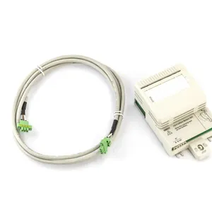
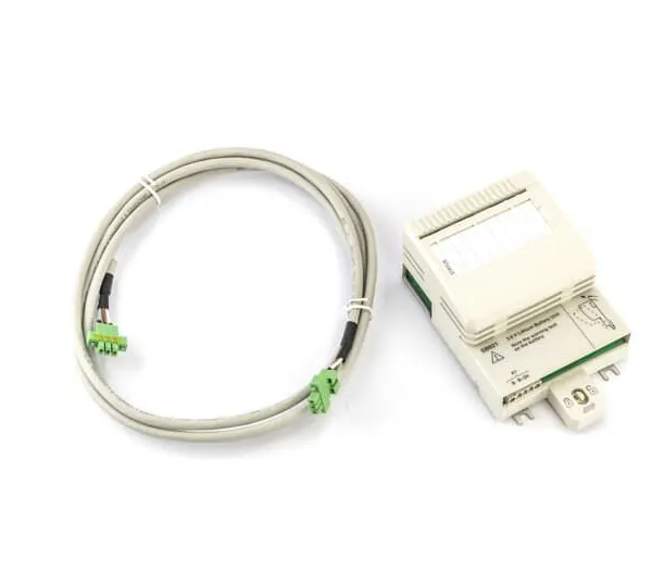
ABB SB821 3BSE018109R1 Battery Unit
Related Products
-
 ABB SS822 3BSC610042R1 Voting DeviceNegotiableMOQ: 1 Piece
 -
ABB SS832 3BSC610068R1 Power Voting UnitNegotiableMOQ: 1 Piece
-
ABB PL810 3BDH000311R0101 Programmable Controller ModuleNegotiableMOQ: 1 Piece
-
ABB PL890 3BDH003115R0101 Programmable Controller ModuleNegotiableMOQ: 1 Piece
-
ABB DO810 3BSE008510R1 Digital Output 24V 16 chNegotiableMOQ: 1 Piece
I. Product Overview
ABB SB821 3BSE018109R1 is a key remote I/O interface module in the AC 800M series distributed control system. Specifically designed for remote expansion and centralized management of I/O signals in decentralized industrial on-site control scenarios, it is widely used in large-scale distributed control projects across industries such as electric power, petrochemicals, metallurgy, rail transit, and intelligent manufacturing. As a core communication bridge between the system's main controller and remote I/O units, this module undertakes core functions including real-time transmission of remote I/O signals, protocol conversion, data processing, and fault diagnosis. It can connect various I/O modules such as digital input/output modules, analog input/output modules, and special function modules, enabling the collection of process parameters and control of actuators distributed in different areas of the industrial site. This significantly reduces on-site wiring costs and enhances the flexibility of system layout.
II. Functional Features
III. Technical Parameters
IV. Working Principle
The working principle of the ABB SB821 3BSE018109R1 remote I/O interface module revolves around the core link of "Communication Establishment - Data Acquisition - Protocol Conversion - Data Transmission - Fault Monitoring", combined with redundancy assurance and fault-tolerance mechanisms to achieve highly reliable data interaction between the main controller and remote I/O modules. The specific process is as follows:
V. Common Fault Handling

Send Inquiry to This Supplier


You May Also Like
-
ABB DO890 3BSC690074R1 Digital Output IS 4 chNegotiableMOQ: 1 Piece
-
ABB DO840 3BSE020838R1 Digital Output 24V S/R 16 chNegotiableMOQ: 1 Piece
-
ABB DO820 3BSE008514R1 Digital Output Relay 8 chNegotiableMOQ: 1 Piece
-
ABB DO814 3BUR001455R1 Digital Output Current 16 chNegotiableMOQ: 1 Piece
-
ABB 87TS01 GJR2368900R1550 Coupl.Mod. CDS Slave MNegotiableMOQ: 1 Piece
-
ABB 87TS01 GJR2368900R2550 Control BoardNegotiableMOQ: 1 Piece
-
ABB 81ET03 GJR2389800R1210 Input Module Temp. SensorsNegotiableMOQ: 1 Piece
-
ABB 81AB03-E GJR2392500R121 Molded Case Circuit Breaker of Tmax T4 SeriesNegotiableMOQ: 1 Piece
-
ABB DI810 3BSE008508R1 Digital Input ModuleNegotiableMOQ: 1 Piece
-
ABB DI820 3BSE008512R1 Digital Input 120V A.c. 8 chNegotiableMOQ: 1 Piece


