
- Guizhou Yuanmiao Automation Equipment Co., Ltd.
-
 1YrAnshun, Guizhou, China
 - Main products: ABB Triconex Foxboro LAM, Bentley Motorola Schneider, Kollmorgen HIMA ALSTOM, Reliance GE HONEYWELL NI、ICS
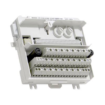
ABB TU839 3BSE046966R1 Extended MTU, 250V
- guizhou
- T/T Other
You May Like
Product Details
| Material | Other, Global universal model | Condition | Other, Global universal model | |
| Task | Other, Global universal model | Mathematical Model | Other, Global universal model | |
| Signal | Other, Global universal model | Customized | Non-Customized | |
| Structure | Other, Global universal model | Operating Temperature | -20℃ to 60℃ | |
| Relative Humidity | 5%-95% (non-condensing) | Dimensions | 150mm × 100mm × 40mm |
Product Description
I. Overview
ABB TU839 3BSE046966R1 is a controller base module, a core hardware support unit of the AC 800M series distributed control system. It is specifically designed to meet the requirements of controller module installation, signal transfer, and power distribution in medium and large-scale industrial process control scenarios. Adopting a standardized modular structure and high-reliability connection design, this base integrates core functions such as multi-channel signal transfer, stable power distribution, modular installation and positioning, and comprehensive electromagnetic compatibility protection. It provides stable mechanical support and efficient signal transmission links for AC 800M series controllers (such as PM861, PM864, etc.).
As a key connection hub between the controller module and the backplane bus in the AC 800M control system, ABB TU839 3BSE046966R1 features excellent system compatibility and expansion flexibility. It can seamlessly adapt to all specifications of AC 800M series controller modules and related expansion modules, and support collaborative work with ABB Process Portal configuration software, HMI human-machine interaction platforms, distributed IO modules (such as AI810, AO810), and upper monitoring systems (SCADA/MES). It is widely used in complex industrial fields such as chemical engineering, petroleum and petrochemical, electric power, metallurgy, and papermaking, providing a solid hardware foundation for the control logic operation, multi-dimensional signal interaction, and stable system operation and maintenance of key equipment such as large-scale reaction devices, generator sets, and production lines. With advantages including high mechanical strength, low contact impedance, strong environmental adaptability, and long service life, this base can adapt to harsh industrial environments such as high temperature, high humidity, heavy dust, and strong electromagnetic interference, ensuring the continuous and stable operation of the core units of the control system.
II. Core Functional Features
ABB TU839 3BSE046966R1 is highly compatible with the architectural design requirements of the AC 800M series control system. Integrating ABB's mature experience in the field of industrial connection technology, it has the following core functional features:

III. Detailed Technical Parameters
IV. Working Principle
As a core support unit of the AC 800M series controller, the working principle of ABB TU839 3BSE046966R1 revolves around four core links: "power distribution - signal transfer - status monitoring - redundancy protection", realizing the efficient collaborative operation of the controller module and other system units. The specific working principle is as follows:
Company Profile
Main products: Covering globally renowned brands: Bently Nevada, Triconex, Woodward, Foxboro, Westinghouse, Reliance, Schneider Modicon, ABB, AB (Allen-Bradley), Motorola, GE Fanuc, Yaskawa, Bosch Rexroth Rexroth, ACSO, YOKOGAWA, Rexroth, NI, ICS Triplex, Kollmorgen, Mitsubishi, MOOG, Emerson, B&R B&r, SST, ALSTOM, KUKA EPRO, LAM HIMA dark Horse, HONEYWELL, prosoft, AMAT, SIEMENS, etc. The product categories include: DCS system accessories, robot system spare parts, large servo system spare parts, etc., which are widely used in power, chemical, metallurgy, intelligent manufacturing and other fields.
Contact Us
- Guizhou Yuanmiao Automation Equipment Co., Ltd.
- Contact nameyezi Chat Now
- AddressXixiu District, Anshun, Guizhou
Product Categories
New Products
-
ABB AI815 3BSE052604R1 Analog Input HART 8 ch
-
ABB AO820 3BSE008546R1 Analog Output 4 ch
-
ABB AO895 3BSC690087R1 Analog Output IS HART 8 ch
-
ABB AO845 3BSE023676R1 Analog Output Module
-
ABB AO650 3BHT300051R1 Analog Output 8ch, 12bit Chan Isol
-
ABB AO890 3BSC690072R1 Analog Output IS 8 ch
-
ABB SB821 3BSE018109R1 Battery Unit
-
ABB SS822 3BSC610042R1 Voting Device
-
ABB SS832 3BSC610068R1 Power Voting Unit
-
ABB PL810 3BDH000311R0101 Programmable Controller Module
-
ABB PL890 3BDH003115R0101 Programmable Controller Module
-
ABB DO810 3BSE008510R1 Digital Output 24V 16 ch
-
ABB DO890 3BSC690074R1 Digital Output IS 4 ch
-
ABB DO840 3BSE020838R1 Digital Output 24V S/R 16 ch
-
ABB DO820 3BSE008514R1 Digital Output Relay 8 ch
-
ABB DO814 3BUR001455R1 Digital Output Current 16 ch
-
ABB 87TS01 GJR2368900R1550 Coupl.Mod. CDS Slave M
-
ABB 87TS01 GJR2368900R2550 Control Board
-
ABB 81ET03 GJR2389800R1210 Input Module Temp. Sensors
-
ABB 81AB03-E GJR2392500R121 Molded Case Circuit Breaker of Tmax T4 Series
-
ABB DI810 3BSE008508R1 Digital Input Module
-
ABB DI820 3BSE008512R1 Digital Input 120V A.c. 8 ch
-
ABB DI818 3BSE069052R1 Digital Input 24V 32 ch
-
ABB DI825 3BSE036373R1 Digital Input 125V SOE 8 ch
Find Similar Products By Category
- Electrical & Electronics > Electrical Control System
Product Tags:
Guizhou Yuanmiao Automation Equipment Co., Ltd.

- Please Enter your Email Address
- Please enter the content for your inquiry.
We will find the most reliable suppliers for you according to your description.
Send Now-
 yezi
Hi there! Welcome to my shop. Let me know if you have any questions.
yezi
Hi there! Welcome to my shop. Let me know if you have any questions.
Your message has exceeded the limit.
- Contact supplier for lowest price
- Customized Request
- Request Sample
- Request Free Catalogs
Your message has exceeded the limit.
-
Purchase Quantity
-
*Sourcing Details
Your inquiry content must be between 10 to 5000 characters.
-
*Email
Please enter Your valid email address.
-
Mobile