



Home > Electrical & Electronics > Electrical Control System > ABB DI810 3BSE008508R1 Digital Input Module
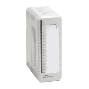
ABB DI810 3BSE008508R1 Digital Input Module
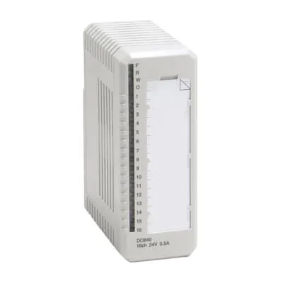
ABB DI810 3BSE008508R1 Digital Input Module photo-1

Negotiable MOQ: 1 Piece (Price negotiable depending on order volume and customization)
Key Specifications
Get Latest Price
Material:
Other, Global universal model
Condition:
Other, Global universal model
Task:
Other, Global universal model
Payment & Shipping
Payment Methods:
Port of Shipment:
guizhou
Delivery Detail:
Delivery time depends on order quantity.
Material Other, Global universal model
Condition Other, Global universal model
Task Other, Global universal model
Mathematical Model Other, Global universal model
Signal Other, Global universal model
Customized Non-Customized
Structure Other, Global universal model
Operating Temperature -20℃ to 60℃
Relative Humidity 5%-95% (non-condensing)
Dimensions 100×160×55mm

I. Overview


ABB DI810 3BSE008508R1 is a digital input module that belongs to the I/O component family of the AC 800M series distributed control system (DCS). Specifically designed for discrete signal acquisition scenarios in industrial processes, it is widely used in fields such as electric power, petrochemicals, metallurgy, papermaking, and water treatment. Its core function is to collect on-site digital signals in real time (e.g., the on-off status of limit switches, pressure switches, level switches, buttons, relay contacts, etc.). After signal isolation, noise filtering, and level conversion, the standardized digital signals are transmitted to the AC 800M controller. It provides accurate and reliable discrete data support for core control logics such as equipment operation status monitoring, interlock protection, and sequence control, serving as a key digital signal acquisition component that connects the on-site execution layer and the control layer in industrial control systems.


This module adopts the standard modular architecture of the AC 800M series, featuring strong system compatibility and expandability. It can be directly inserted into compatible slots of standard I/O racks (such as CI854 and CI855) and realizes high-speed communication with the controller via fieldbuses like PROFIBUS DP or EtherNet/IP. Adhering to industrial-grade high-reliability design standards, it incorporates designs such as multiple electromagnetic interference suppression, wide-temperature operating range optimization, and redundant configuration support, enabling stable adaptation to harsh industrial environments with high temperatures, heavy dust, strong vibrations, and intense electromagnetic interference. Relying on ABB's dedicated signal processing technology, it ensures the real-time performance and accuracy of digital signal acquisition, making it a core digital input component for building highly reliable industrial process control systems.


II. Technical Specifications


Parameter Category Parameter Name Specific Parameters Unit
Basic Parameters Model Number ABB DI810 3BSE008508R1 -

Product Type High-density Digital Input (DI) Module -

Series ABB AC 800M Distributed Control System -

Compatible Rack AC 800M Standard I/O Racks (e.g., CI854, CI855, CI856) -

Overall Dimensions (L×W×H) 100×160×55 mm

Installation Method I/O Rack Slot Installation (with mechanical latch and anti-misinsertion design) -


Acquisition Performance Parameters

Number of Input Channels 16 independent digital input channels with mutual isolation between channels Channel(s)

Input Signal Type DC digital signals (compatible with dry contacts and wet contacts) -

Input Voltage Range 24VDC (standard), compatible with wide-range power supply of 19.2~30VDC VDC

Input Current Typical 4mA per channel (when signal is active), maximum 6mA mA

Response Time Configurable: 1ms (standard mode), 0.1ms (high-speed mode), delay jitter ≤0.05ms ms

Signal Detection Method Positive logic (high-level active: DC 11~30VDC = "1", DC 0~5VDC = "0"), supporting software-configurable negative logic -


Electrical & Communication Parameters

Power Supply Voltage DC 5V (logic power) + DC 24V (signal power) supplied by I/O rack, supporting redundant power supply V

Maximum Power Consumption Logic power: ≤2W; Signal power: ≤12W (when 16 channels are fully loaded) W

Isolation Performance Between channels: 500VAC/1min; Between channels and backplane/power supply: 1500VAC/1min; Between power supply and backplane: 1000VAC/1min VAC/min

Communication Method Communicates with the controller via I/O rack bus, supporting PROFIBUS DP (12Mbps) and EtherNet/IP (100Mbps), and enabling cyclic and acyclic data transmission Mbps


Environmental Parameters


Operating Temperature Range


-20~60℃ (standard operating range), -40~70℃ (extended operating range, short-term)


Storage Temperature Range -40~85℃

Relative Humidity 5%~95% (no condensation, compliant with IEC 60068-2-3 standard), withstanding short-term high humidity of 98% %

Electromagnetic Interference Immunity Compliant with IEC 61000-4-2/3/4/6/8 standards, ESD ±15kV (air)/±8kV (contact), RF interference suppression ≥40dB, burst immunity ±2kV -

3BSE020838R1


III. Functional Features


  • Seamless Integration with AC 800M System, Efficient Deployment: The module adopts the unified hardware interface and communication protocol of the AC 800M series. It can be directly inserted into any compatible slot of standard I/O racks, enabling "plug-and-play" integration without the need for additional adapters, custom drivers, or jumper adjustments. It conducts high-speed data interaction with AC 800M controllers (e.g., PM864, PM866) via the I/O rack bus. The total delay from signal acquisition to controller reception is ≤2ms in standard mode and can be reduced to ≤0.2ms in high-speed mode, meeting the timing requirements of high-speed sequence control. It fully supports ABB Control Builder M configuration software, allowing users to configure response time, define logic levels, set filter parameters, and define alarm thresholds for each channel through a graphical interface. It seamlessly links with the system's control logic and monitoring interface, significantly shortening the system commissioning cycle.

  • High-Density Channel Design, High Space Utilization: Equipped with 16 independent input channels, the module has dimensions of only 100×160×55mm, achieving a channel density per unit volume of 0.016 channels/mm³, which is over 30% higher than that of similar products. The 16 channels are divided into 4 groups (4 channels per group), with independent isolation design between groups. This allows connection of digital signals with different potentials to avoid inter-channel signal interference. Two wiring options are available for channels: spring terminals and screw terminals. Spring terminals support quick wiring, reducing wiring time by 50% compared to traditional terminals; screw terminals feature anti-loosening design to adapt to vibrating industrial on-site environments. Both wiring methods support wire diameters of up to 1.5mm².

  • Wide Voltage Compatibility and Flexible Detection, Strong Adaptability: It supports a wide signal power supply range of 19.2~30VDC, compatible with common 24VDC standard power fluctuations in industrial sites, eliminating the need for additional voltage stabilization equipment. It is compatible with two input modes for signals: dry contacts and wet contacts. For dry contact input, the module provides 24VDC excitation power internally; for wet contact input, it directly collects on-off signals from external power supplies. These two modes can be flexibly configured via software without hardware jumpers. It supports configurable positive and negative logic. In default positive logic, 11~30VDC is "1" and 0~5VDC is "0"; the logic is reversed in negative logic mode, enabling adaptation to signal output characteristics of sensors from different manufacturers.

  • Multiple Isolation and Anti-Interference, Adaptation to Harsh Environments: It adopts a triple electrical isolation design: "channel group-channel group", "channel-backplane", and "power supply-backplane", with isolation voltages of 500VAC/1min (between groups), 1500VAC/1min (between channels and backplane), and 1000VAC/1min (between power supply and backplane) respectively. This effectively blocks interference from on-site ground loops, power fluctuations, and equipment electromagnetic radiation on signal acquisition. Each channel is equipped with an RC hardware filter circuit and a TVS surge suppression component, which can filter high-frequency noise below 100kHz and withstand transient surge impacts of ±2kV. Compliant with IEC 61000-4 series electromagnetic interference immunity tests, it achieves RF interference suppression of ≥40dB in high-interference environments such as high-voltage motors, frequency converters, and welding machines, ensuring the stability and accuracy of signal acquisition and adapting to various harsh industrial scenarios.

  • Configurable Response Time, Flexible Scene Adaptation: It supports software-configurable response time, offering four optional levels: 0.1ms (high-speed mode), 1ms (standard mode), 10ms (anti-interference mode), and 100ms (slow-changing mode). High-speed mode is suitable for scenarios such as high-speed counting and fast switch status monitoring, where the 0.1ms response time can accurately capture high-frequency on-off signals. Anti-interference mode and slow-changing mode are suitable for scenarios with heavy dust and strong vibrations; by extending the response time, false signals are filtered out to avoid misoperation of control logic. Different channels can be grouped and configured with different response times. For example, the first 8 channels can be configured in high-speed mode to monitor the status of high-speed valves, while the last 8 channels can be configured in anti-interference mode to monitor ordinary switches, meeting diverse scenario requirements.

  • Full-Dimensional Diagnosis and Early Warning, Convenient and Efficient Operation & Maintenance: It is equipped with comprehensive online diagnosis functions, enabling real-time monitoring of the operating status of the module's internal core components (logic circuits, communication interfaces, power modules), input channels (signal short circuit, open circuit, overvoltage, undervoltage), and power supply status (logic power failure, signal power failure). Diagnostic information includes fault type, faulty channel, fault occurrence time, and fault level, which can be viewed remotely via Control Builder M software or displayed intuitively on-site through LED indicators on the front of the module (power indicator, operation indicator, channel status indicator, fault indicator). It supports fault early warning: when potential fault signs such as signal level fluctuations and abnormal power supply voltage are detected, early warning signals are sent in advance to assist operation and maintenance personnel in conducting predictive maintenance.

  • Industrial-Grade Reinforced Design, Excellent Environmental Adaptability: It adopts industrial-grade high-reliability components and an all-metal housing design. The housing has excellent heat dissipation performance and mechanical strength, enabling rapid heat dissipation from the module during operation and ensuring stable operation within the standard temperature range of -20~60℃ and the short-term extended temperature range of -40~70℃. It has passed vibration tests (5~150Hz, 3g acceleration) in accordance with IEC 60068-2-6 and shock tests (15g acceleration, 11ms duration) in accordance with IEC 60068-2-27, adapting to equipment operation vibrations and transportation/installation shocks. The module has an IP20 protection rating and is equipped with a dust-proof panel design, which can effectively prevent dust intrusion in industrial sites and adapt to harsh operating environments such as power generation workshops, chemical plants, and metallurgical plants with heavy dust and high temperatures.

  • Redundant Configuration Support, Significantly Improved Availability: It supports two redundant configuration methods: module-level redundancy and channel-level redundancy. For module-level redundancy, two DI810 modules can be configured in master-standby mode; when the master module fails, the controller automatically switches to the standby module to receive data, with a switching time of ≤1ms. For channel-level redundancy, the same digital signal can be connected to channels of two different modules to realize "dual-acquisition" data comparison; when one channel fails, the data from the other channel is automatically used. It supports hot-swapping: under the condition that the system is not shut down and the controller continues to operate, the module can be directly inserted or removed for maintenance and replacement. After the module is removed, the controller automatically marks the corresponding channel as "faulty" and executes the preset safety logic; after inserting a new module, configuration synchronization is completed and operation is restored within 5 seconds, significantly shortening maintenance downtime.

IV. Working Principle


As the digital sensing core of the AC 800M control system, the ABB DI810 3BSE008508R1 module adopts the core workflow of "initialization configuration - signal acquisition - conditioning and filtering - level conversion - data transmission - diagnostic feedback" to realize accurate acquisition and reliable transmission of digital parameters in industrial processes. The specific workflow is as follows:


  1. Module Initialization and Configuration Loading: After the module is installed in the AC 800M I/O rack and powered on, it automatically starts the initialization process. First, it performs a hardware self-test, sequentially checking the integrity of the logic processing unit, communication interface, power module, and 16 input channels. After passing the self-test, it establishes a communication connection with the controller via the I/O rack bus and receives configuration parameters issued by the controller, including response time, signal type (dry/wet contact), logic level (positive/negative logic), filter parameters, and fault thresholds for each channel. After initialization, the module sends a "ready" signal to the controller, the LED operation indicator remains on, and it enters the normal working mode. If the self-test fails or the configuration parameters fail to load correctly, a fault alarm is triggered immediately, fault codes are uploaded via the communication bus, and the corresponding fault indicator is lit.

  2. Digital Signal Acquisition and Conditioning: The on-off status of on-site digital equipment (e.g., pressure switches) is converted into 24VDC electrical signals, which are transmitted to the corresponding input channels of the module. The module performs differentiated acquisition based on the signal type configured for the channel: for dry contact signals, the module provides 24VDC excitation power internally; when the contact is closed, a circuit is formed, and the channel detects current. For wet contact signals, electrical signals from external power supplies are directly received without internal power supply from the module. The collected signals first pass through the TVS surge suppression component to suppress transient overvoltage impacts, and then enter the RC hardware filter circuit to filter high-frequency noise and pulse interference, ensuring signal stability.

  3. Level Conversion and Signal Determination: The conditioned analog electrical signals are sent to the level conversion circuit and converted into digital signals (TTL level) recognizable by the module's internal logic circuits. The logic processing unit determines the signals based on the configured logic level parameters: in positive logic mode, a detected voltage of 11~30VDC is determined as digital "1" (valid signal), and a detected voltage of 0~5VDC is determined as digital "0" (invalid signal); the determination rule is reversed in negative logic mode. At the same time, the logic processing unit performs delayed determination on the signals according to the configured response time parameters to avoid misdetermination caused by transient interference. For example, in the 10ms anti-interference mode, the signal status is confirmed only after a stable level is continuously detected for 10ms.

  4. Data Transmission and Redundancy Linkage: The determined digital signals are transmitted to the AC 800M controller via the I/O rack bus, providing data support for logics such as sequence control and interlock protection. Data transmission adopts a cyclic transmission method, with a transmission cycle of 1ms in standard mode and 0.1ms in high-speed mode. It also supports acyclic transmission for uploading diagnostic information. If redundant mode is configured: for module-level redundancy, the master module synchronizes collected data and working status to the standby module in real time; when the master module fails, the standby module takes over data transmission within 1ms. For channel-level redundancy, the controller compares the same signal collected by two channels; if the two signals are consistent, the signal is used; if inconsistent, a channel fault alarm is triggered and the abnormal channel is marked.

  5. Real-Time Diagnosis and Fault Handling: During operation, the module continuously performs full-dimensional diagnosis: ① Hardware diagnosis: periodically checks the voltage of logic circuits, stability of communication links, output status of power modules, and integrity of isolation circuits; ② Signal diagnosis: real-time monitors the signal level of input channels (e.g., a detected voltage of 30~40VDC is determined as overvoltage, and a voltage of 0~0.5VDC with current is determined as short circuit), signal stability (level fluctuation frequency exceeding the threshold is determined as abnormal), and contact bounce; ③ Power supply diagnosis: monitors voltage fluctuations of the logic power supply (DC 5V) and signal power supply (DC 24V); a voltage beyond the range of 19.2~30VDC is determined as power supply abnormality. When a fault is diagnosed, three actions are executed immediately: ① Upload detailed information such as fault type, channel, and time to the controller via the communication bus; ② Light up the corresponding fault indicator on the front of the module (global fault indicator or channel fault indicator); ③ If redundancy is configured, automatically trigger the redundancy switching logic to ensure continuous data output.
Product Tags: DI810 , 3BSE008508R1

Send Inquiry to This Supplier

Message
0/5000

Want the best price? Post an RFQ now!
Gold Verified Supplier
1Yr
Verified Business License
Business Type
Trading Company
Year Established
2014
Factory Size
1,000-3,000 square meters
Product Certifications
SA8000


