



Home > Electrical & Electronics > Electrical Control System > ABB DO814 3BUR001455R1 Digital Output Current 16 ch
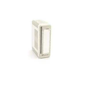
ABB DO814 3BUR001455R1 Digital Output Current 16 ch
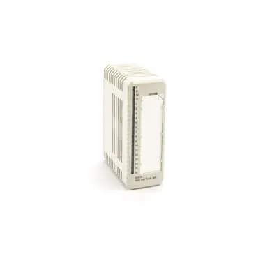
ABB DO814 3BUR001455R1 Digital Output Current 16 ch photo-1

Negotiable MOQ: 1 Piece (Price negotiable depending on order volume and customization)
Key Specifications
Get Latest Price
Material:
Other, Global universal model
Condition:
Other, Global universal model
Task:
Other, Global universal model
Payment & Shipping
Payment Methods:
Port of Shipment:
guizhou
Delivery Detail:
Delivery time depends on order quantity.
Material Other, Global universal model
Condition Other, Global universal model
Task Other, Global universal model
Mathematical Model Other, Global universal model
Signal Other, Global universal model
Customized Non-Customized
Structure Other, Global universal model
Operating Temperature -25℃ to 70℃
Relative Humidity 5%-95% (non-condensing)
Dimensions 100×160×80mm

I. Product Overview


ABB DO814 3BUR001455R1 is a high-performance digital output module, belonging to the I/O unit family of the AC 800M system, and serving as a key interface component between the system and on-site executive devices. The main function of this module is to receive digital control commands from the AC 800M controller, convert them into stable and reliable switching signal outputs, and drive various on-site executive devices such as contactors, solenoid valves, indicator lights, and relays. It is widely used in industrial fields such as electric power, petrochemical, metallurgy, water treatment, and intelligent manufacturing, providing accurate digital output support for logical control and sequence control in various production processes.


Based on ABB's advanced industrial I/O processing technology, this module adopts a high-performance microprocessor and high-reliability power driver chips, featuring core characteristics such as high output reliability, strong anti-interference capability, comprehensive diagnostic functions, hot-swap support, and good system compatibility. It has passed the IEC 61131-2 industrial control equipment standard certification, IEC 61000-6-2/6-4 electromagnetic compatibility certification, and UL 508 industrial safety certification. It can operate stably in harsh industrial environments with a wide temperature range of -25℃~70℃, high humidity, high dust, and strong electromagnetic interference. It perfectly adapts to the distributed I/O topology of the AC 800M system and meets the requirements of high reliability, high real-time performance, and easy maintainability for digital output control in industrial sites.


II. Functional Features


  • Multi-channel Independent Control and Flexible Configuration: The module integrates 16 independent digital output channels, and each channel can be flexibly configured as PNP or NPN output mode through ABB Control Builder M configuration software, adapting to different types of on-site executive devices. It can meet diverse control needs without replacing hardware. Each channel supports a maximum output current of 2A, and the total output current can reach 10A, which can drive multiple medium and low-power executive devices simultaneously, reducing the number of modules configured and lowering system costs. The channels adopt a 500V AC isolation design, effectively avoiding signal interference between channels and ensuring the independence and stability of each output signal.


  • Comprehensive Protection Mechanism to Ensure Operational Safety: The module is equipped with independent overcurrent protection and short-circuit protection circuits for each output channel. When the output current of a channel exceeds the rated value or a short circuit occurs, it can quickly cut off the output circuit, limiting the maximum current to ≤2.5A to avoid damage to the module and on-site executive devices. It also has a power reverse polarity protection function. When the positive and negative poles of the power supply are reversed, the built-in protection diode can block the reverse current to prevent the module's power circuit from being burned. In addition, the module supports overvoltage protection. When the supply voltage exceeds 26.4V, it automatically enters a voltage stabilization state to ensure the stable operation of internal circuits. After the fault is eliminated, the protection circuit can automatically reset without manual intervention, improving maintenance convenience.


  • Comprehensive Diagnostic Functions and Status Monitoring: The module has built-in dual diagnostic mechanisms at the channel level and module level. A dedicated microprocessor monitors the output current, voltage status, and line connection of each channel in real time, enabling accurate diagnosis of faults such as channel short circuits and overcurrent. It also monitors the module's power supply voltage and communication link status to promptly detect power faults and communication interruptions. Diagnostic information includes the fault channel number, fault type, and fault occurrence timestamp, which can be displayed in real time through Control Builder M software and uploaded to the AC 800M controller and background monitoring system via the communication bus. The front of the module is equipped with clear LED indicators, with each channel corresponding to an "ON/OFF" status indicator, and the module as a whole is equipped with "power", "communication", and "fault" LED indicators. On-site operation and maintenance personnel can quickly judge the operation status of the module and channels through the indicators, shortening the fault troubleshooting time.


  • Hot-swap Support and Convenient Maintenance: The module adopts ABB standard hot-swap mechanical structure and circuit design, supporting plug-in replacement of the module while the AC 800M system is not shut down and on-site equipment is operating normally. During the plugging process, the isolation circuit inside the module can ensure that it will not interfere with the system bus and other modules. The replaced module can automatically synchronize configuration parameters with the controller without reconfiguring hardware and software programming, greatly shortening maintenance downtime and improving system availability. The module adopts a modular design, and the terminals use spring-type or screw-type quick wiring methods, which are firm and easy to disassemble, reducing the difficulty of on-site installation and commissioning.


  • High Compatibility and System Integration Advantages: The module perfectly adapts to the ABB AC 800M distributed control system and can achieve high-speed communication with the AC 800M controller through interface modules such as CI854 (PROFIBUS DP interface) or CI858 (Profinet interface). The communication rate can reach up to 12Mbps, and the data transmission delay is ≤1ms, meeting the strict requirements of industrial sites for real-time control. It supports seamless integration with the ABB Industrial IT Symphony Plus control system, enabling centralized monitoring, parameter configuration, and fault management of the module through the system platform. At the same time, the module supports the access of third-party SCADA systems, realizing data interaction through standard communication protocols and improving the flexibility of system integration.


  • High Reliability and Wide Environmental Adaptability: It adopts a fanless natural heat dissipation design, and the module shell is made of high-strength engineering plastic, combined with an optimized internal circuit layout, ensuring the module operates stably within a wide temperature range of -25℃~70℃. Core components are all industrial-grade high-reliability products, such as imported power MOS tubes (service life ≥100,000 hours), high-precision protection chips, and gold-plated connectors (plugging times ≥1,000 times). Combined with strict environmental stress screening (ESS) tests, including high-temperature aging, low-temperature impact, vibration test, electromagnetic compatibility test, etc., the mean time between failures (MTBF) of the module is ≥300,000 hours, which can adapt to the long-term continuous operation requirements in fields such as electric power and petrochemical industry.


3BUR001455R1


III. Technical Parameters


Parameter Category Parameter Name Specific Parameters Unit
Basic Parameters Model Number ABB DO814 3BUR001455R1 -

Product Type Digital Output Module for AC 800M System -

Overall Dimensions (L×W×H) 100×160×80 mm

Weight Approximately 0.8 kg

Installation Method Mounting on AC 800M Standard I/O Rack (Compatible with CI854/CI858 Interface Modules) -


Power Supply Parameters


Supply Voltage


DC 24V±10%, supporting single-channel/dual-channel power supply


V DC


Rated Supply Current 2A (at full load operation) A

Power Consumption ≤15W W

Power Supply Isolation 2500V AC, between input and system V AC


Output Channel Parameters


Number of Output Channels

16 channels, independently configurable Channel

Output Signal Types PNP/NPN configurable, dry contact output -

Rated Output Voltage DC 24V V DC

Maximum Output Current per Channel 2A A

Total Maximum Output Current 10A (when all channels are working simultaneously) A

Output Response Time ≤1ms (from command reception to output state switching) ms

Channel Isolation 500V AC, between channels and between channel and system V AC


Protection & Diagnosis Parameters

Protection Functions


Overcurrent protection, short-circuit protection, reverse polarity protection, overvoltage protection

-

Diagnostic Functions Channel short-circuit diagnosis, overcurrent diagnosis, power supply fault diagnosis, module communication fault diagnosis, output state feedback diagnosis -

Fault Record Capacity 500 records (with timestamp and fault channel information) Record

Status Indication "ON/OFF" LED indicator for each channel; "Power", "Communication", "Fault" LED indicators for the module -


Communication & Environmental Parameters


Communication Interface

PROFIBUS DP/Profinet (via CI854/CI858 interface modules) -

Operating Temperature Range -25~70℃

Mean Time Between Failures (MTBF) ≥300000 hours hour


IV. Working Principle


The working principle of the ABB DO814 3BUR001455R1 digital output module revolves around the core link of "command reception - signal processing - output driving - status feedback - diagnostic protection", combining high-precision signal processing and high-reliability driving technology to achieve precise control of on-site executive devices. The specific process is as follows:


  1. Power Supply and System Initialization: After the module is connected to a DC 24V power supply, the built-in power management module rectifies, filters, and stabilizes the input power, outputting a stable +5V DC voltage to power core units such as the microprocessor, communication module, and diagnostic circuit. The power management module monitors the supply voltage and current status in real time. When overvoltage, undervoltage, reverse polarity, or other abnormalities are detected, it immediately triggers a power fault alarm and cuts off the power supply to non-core circuits to protect the core components of the module. After power-on, the module automatically executes the initialization program. The microprocessor self-checks the memory, communication interface, driver chip, and diagnostic circuit. After passing the self-check, it loads user configuration parameters (such as channel output mode, protection threshold, etc.) and establishes a communication connection with the controller. After initialization, the module enters the ready state; if the self-check fails, the fault indicator flashes red and records the fault code.


  2. Control Command Reception and Processing: The module establishes a communication connection with the AC 800M controller through an interface module (CI854/CI858) and receives digital control commands (such as "ON" and "OFF" commands) from the controller in real time. The control commands are sent to the microprocessor after photoelectric isolation. The microprocessor decodes and validates the commands, determining whether they conform to the channel configuration mode (PNP/NPN) and output permission requirements. After passing the validation, the microprocessor generates corresponding drive control signals according to the command content and distributes them to the corresponding output channels; if the command is invalid, the microprocessor will refuse to execute it, record the command error information, and feed it back to the controller through communication.


  3. Output Driving and On-site Control: The drive control signals are sent to the corresponding power drive circuits. The power drive circuits control the conduction and shutdown of power MOS tubes according to the PNP or NPN mode configured for the channel, thereby converting the DC 24V power signal into a switching output signal. When receiving an "ON" command, the power MOS tube conducts, and the output channel outputs a DC 24V voltage signal to drive on-site executive devices (such as contactors, solenoid valves) to act; when receiving an "OFF" command, the power MOS tube shuts down, the output channel has no voltage output, and the executive device stops working. Each drive circuit is equipped with an independent current detection resistor to monitor the output current in real time, providing data support for overcurrent and short-circuit diagnosis.


  4. Status Feedback and Diagnostic Monitoring: The actual operating status (voltage, current) of the output channel is processed by the signal conditioning circuit and then sent to the microprocessor for analysis. The microprocessor compares the actual output status with the control command to realize closed-loop feedback of the output status and ensure the accurate execution of the control command. At the same time, the diagnostic unit monitors the current value of each channel in real time. When the current exceeds 2A (overcurrent) or instantly exceeds 2.5A (short circuit), it immediately triggers the protection circuit to cut off the output and records the fault information; it monitors whether the power supply voltage is within the range of 21.6V~26.4V, and triggers a power fault alarm if it is out of range; it monitors the signal integrity of the communication link, and triggers a communication fault alarm if no controller command is received for 3 consecutive communication cycles. Fault information is uploaded to the controller through the communication bus, and the corresponding indicator light sends an alarm signal.


  5. Redundancy and Fault Recovery (Optional Configuration): When the system is configured in 1+1 redundancy mode, the main module and the redundant module synchronize control commands and operating status in real time through the communication link. The redundancy management unit monitors the operating status of the main module in real time. When the main module fails, the redundant module can take over the output task of the main module within ≤10ms to ensure the continuous operation of on-site executive devices. After the faulty main module is repaired, it can be restored to the main module or run as a redundant module through software settings. For single-module configuration, when an overcurrent or short-circuit fault occurs in a channel, after the protection circuit acts, if the fault is eliminated within 10 seconds, the module can automatically resume output; if the fault persists, the module will lock the faulty channel, and manual reset is required to resume operation.

Product Tags: DO814 , 3BUR001455R1

Send Inquiry to This Supplier

* Message
0/5000

Want the best price? Post an RFQ now!
Verified Business License
Business Type
Trading Company
Year Established
2014
Factory Size
1,000-3,000 square meters
Product Certifications
SA8000

