Material
Other, Global universal model
Condition
Other, Global universal model
Task
Other, Global universal model
Mathematical Model
Other, Global universal model
Signal
Other, Global universal model
Customized
Non-Customized
Structure
Other, Global universal model
Operating Temperature
-40°C to +70°C
Relative Humidity
5%~95% (non-condensing)
Storage temperature
-50℃ to 85℃
Dimensions
220mm × 180mm × 100mm
I. Overview
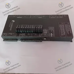
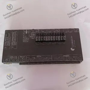
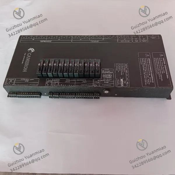
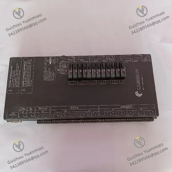
The CAMERON AAP3798102-00031 is a dedicated control module for the energy industry, with its core positioning as a "valve actuator drive and pressure safety control hub for high-pressure scenarios".
Its core value lies in integrating Cameron's technical expertise in high-pressure fluid control and safety redundancy, providing an integrated solution of "precision motion control + real-time pressure monitoring + emergency fault protection" for critical equipment such as wellhead valves on oil drilling platforms and block valves in long-distance natural gas pipelines. It is suitable for harsh scenarios in the energy sector, including high wellhead pressure (≤15,000 psi), high corrosion (containing H₂S/CO₂), and extreme field temperature and humidity (-40℃ to 70℃), ensuring the safe and stable operation of energy extraction and transportation processes.
This module features explosion-proof and anti-corrosion enhanced design, supports seamless integration with Cameron's wellhead control systems (e.g., CAMERON ESD systems), and combines control precision with safety compliance. It serves as a core component enabling "controllability, measurability, and protectability" for high-pressure equipment in the energy industry.

II. Technical Specifications
(I) Performance Parameters
(II) Environmental and Reliability Parameters
(III) Physical and Installation Parameters
III. Functional Features
(I) High-Pressure Adaptation and Extreme Environment Resistance
High-Pressure Sealing and Measurement: 15,000 psi pressure measurement range + API 6A standard high-pressure interface, suitable for high-pressure working conditions of wellhead drilling fluid and natural gas. The pressure measurement accuracy of ±0.1% FS ensures no deviation in pressure monitoring, avoiding safety risks caused by inaccurate measurement;
Enhanced Explosion-Proof and Anti-Corrosion: Ex d IIC T6 Ga explosion-proof class resists the risk of flammable gas explosion in hazardous areas; NACE MR0175 anti-corrosion treatment withstands corrosive media containing H₂S/CO₂; IP67 protection copes with rainy and dusty field environments, ensuring long-term stable operation of the module;
Stable Operation at Wide Temperatures: The -40℃ to 70℃ wide-temperature design ensures no jamming at low temperatures (no freezing of actuator drive) and no failure at high temperatures (electronic components withstand 70℃), suitable for extreme field climates such as oilfields and gas fields.
(II) Precision Control and Safety Protection
Precise Valve Control: ±1% opening control accuracy enables "fine adjustment" of valves (e.g., flow adjustment of wellhead choke valves); the emergency valve closing response time of ≤500ms meets the requirements of ESD (Emergency Shutdown System), preventing pipeline overpressure leakage;
Pressure Closed-Loop Protection: Real-time monitoring of pipeline pressure (10Hz sampling). When the pressure exceeds 15,000 psi or is lower than 1,000 psi, it automatically triggers valve closing or alarm, and links with the wellhead ESD system through DO output signals to form a "monitoring-judgment-protection" closed loop;
Fault Emergency Mechanism: Automatically enters "emergency mode" (maintains current valve opening to avoid misoperation) when communication is interrupted; relies on backup power to complete emergency valve closing in case of power failure, minimizing fault risks.
(III) Flexible Integration and Usability
Multi-System Compatibility: Supports HART/Modbus dual protocols, and can be directly connected to Cameron's wellhead control cabinet, Schlumberger OASyS SCADA system, and also compatible with third-party DCS (e.g., Emerson DeltaV) without additional protocol converters;
Local and Remote Dual Control: Locally, pressure can be viewed through the LCD screen and emergency operations can be performed via physical buttons; remotely, opening commands can be issued and fault alarms received through the SCADA system, meeting both on-site operation and maintenance and remote monitoring needs;
Simplified Maintenance: The HART protocol supports on-line calibration of pressure sensors (no need to disassemble the module); LED indicators + LCD screen intuitively display fault types (e.g., "pressure sensor fault", "actuator overload"), reducing maintenance time.
(IV) Compliance and Traceability
Industry Standard Compliance: Complies with core energy industry standards such as API 6A (wellhead equipment), API 570 (pipeline maintenance), and NACE MR0175 (anti-corrosion), meeting the safety access requirements for oil and natural gas extraction and transportation;
Data Traceability: Supports storage of 1,000 pressure anomaly and valve action records (with timestamps), and data is not lost when power is off, facilitating post-accident traceability and analysis and meeting safety production supervision requirements.
IV. Application Fields
(I) Oil Drilling: Wellhead Valve Control
Application Scenario
In onshore/offshore oil drilling platforms, it is necessary to control the gate valves/choke valves of wellhead Blowout Preventers (BOP) and monitor the drilling fluid circulation pressure (normal range: 0-10,000 psi; emergency valve closing is required when abnormal pressure exceeds 12,000 psi). The module is required to withstand drilling platform vibration (≤5g) and salt spray corrosion, with an emergency valve closing response time of ≤1s.
Module Function Implementation
Pressure Monitoring: Real-time collection of drilling fluid pressure (0-15,000 psi), with a sampling rate of 10Hz to capture pressure pulses; the accuracy of ±0.1% FS ensures no omission of abnormal pressure;
Valve Control: Drives the BOP hydraulic actuator (3000 psi hydraulic oil), receives "open/close/throttle" commands from the SCADA system remotely, and achieves precise adjustment of drilling fluid flow with ±1% opening control accuracy;
Safety Protection: When the pressure exceeds 12,000 psi, it triggers emergency valve closing within 500ms, and at the same time activates the platform ESD by outputting signals through DO to shut down the drilling pump, avoiding wellhead overflow risks.
(II) Natural Gas Transportation: Long-Distance Pipeline Block Valve Control
Application Scenario
In long-distance natural gas pipelines, it is necessary to control pipeline block valves (DN 200, full closing/opening time ≤3s) and monitor pipeline pressure (normal range: 4,000-8,000 psi; blocking is required when pressure exceeds 10,000 psi or is lower than 2,000 psi). The module is required to withstand -35℃ low winter temperatures and H₂S corrosion along the pipeline, and support remote communication (50km away from the central control room).
Module Function Implementation
Environmental Adaptation: NACE MR0175 anti-corrosion treatment resists H₂S corrosion; -40℃ wide-temperature design copes with low winter temperatures; IP67 protection adapts to field rainy weather;
Pressure and Valve Linkage: When the pressure exceeds 10,000 psi or is lower than 2,000 psi, it automatically drives the block valve actuator (electric, DC 48V) to complete full closing within 3s, and uploads the "blocking reason" to the central control room through Modbus RTU;
Remote Monitoring: The Modbus RS-485 interface realizes 50km long-distance communication through a signal amplifier, allowing the central control room to view pressure and valve status in real time and issue "manual valve opening" commands (after fault elimination).
(III) Oil and Gas Extraction: Downhole Safety Valve Control
Application Scenario
During the production of oil and gas wells, it is necessary to control the opening/closing of the Subsurface Safety Valve (SSSV) (to maintain stable oil and gas flow and cut off downhole fluid in case of abnormalities) and monitor downhole pressure (normal range: 5,000-8,000 psi). The module needs to be installed on the wellhead Christmas tree, withstanding H₂S/CO₂ mixed corrosion and high temperatures (wellhead temperature ≤65℃).
Module Function Implementation
Anti-Corrosion and Explosion-Proof: Ex d IIC T6 Ga explosion-proof class is suitable for hazardous wellhead areas; NACE MR0175 anti-corrosion treatment resists acidic fluid corrosion, ensuring long-term reliable operation;
Valve Drive: Drives the downhole SSSV electric actuator (DC 24V), receives "open/close" commands from the surface control cabinet, with an action response time of ≤500ms, meeting the demand for downhole emergency cut-off;
Status Feedback: Collects the "open/close in place" signal of the safety valve through DI, judges whether the valve operates normally based on pressure data, and triggers local alarm lights and remote SCADA alarms in case of abnormalities (e.g., "valve not in place after opening command is issued").
V. Operation Guide
(I) Installation Steps
1. Hardware Installation
Preparation: Confirm that the module model (AAP3798102-00031) matches the application scenario (e.g., explosion-proof version is required for wellheads); Check the installation environment (pressure interface, power supply, communication cable routing); In hazardous areas, ventilate in advance to detect flammable gas concentration (
Fixing and Wiring:
Installation: Fix it near the wellhead Christmas tree/pipeline valve using API 6A flanges, ensuring the pressure interface is vertically downward (to avoid liquid accumulation); Tighten the mounting bolts according to API standards (e.g., torque of M16 bolts is 40 N・m);
Pressure Interface: Connect the 1/2” NPT high-pressure pipe to the pipeline pressure point; Wrap PTFE sealing tape (3-5 turns) around the interface to ensure high-pressure sealing without leakage;
Power Supply and Communication: Connect dual DC 24V power supplies to the "Power A/B" terminals respectively (reverse connection protection is provided); Connect the ground wire (PE) to the wellhead grounding grid (ground resistance ≤1Ω); Use shielded twisted-pair cables for RS-485 communication lines (single-end grounding of the shield layer), and connect HART lines to dedicated debugging terminals;
Actuator Connection: Connect the power cable of the electric actuator to the "Motor Out" terminal (pay attention to forward/reverse polarity); Connect the control cable of the hydraulic actuator to the "Hydraulic Valve" terminal.
2. Initial Configuration (HART Debugging)
Tool Preparation: Connect a HART handheld communicator (e.g., Emerson 475) to the HART terminal of the module, and select the "CAMERON AAP3798102" device library on the communicator;
Basic Configuration: Set the pressure measurement range (e.g., 0-12,000 psi, matching actual working conditions), pressure over-limit thresholds (e.g., high limit 12,000 psi, low limit 2,000 psi), and actuator action time (e.g., valve closing time 3s);
Communication Configuration: Set the Modbus address (e.g., 1-31) and baud rate (9600bps, consistent with the SCADA system), and enable the HART on-line monitoring function.
(II) Parameter Configuration (Core Functions)
1. Pressure Protection Configuration
Local Configuration: Enter "Pressure Setup" through the module's LCD screen, set "High Pressure Trip" (high limit 12,000 psi) and "Low Pressure Trip" (low limit 2,000 psi), and select the trigger action ("Trip→Close Valve" or "Trip→Alarm");
Remote Configuration: Enter the "Pressure Protection" interface in the SCADA system, issue pressure threshold parameters, and the module will automatically synchronize to the local after receiving the parameters. After configuration, a test is required (simulate pressure over-limit to confirm valve action).
2. Valve Control Configuration
Opening Calibration: Press the "Calibrate" button locally; the module drives the valve to perform a full stroke from 0% to 100%, automatically records the feedback signal corresponding to each opening, and completes calibration (to ensure ±1% accuracy);
Action Mode: Set "Normal Mode" (remote command control) and "Emergency Mode" (local button/pressure over-limit control); Emergency Mode has higher priority than Normal Mode to ensure safety;
Response Time: Adjust "Actuator Response Time" in the HART handheld communicator (e.g., 500ms for emergency valve closing, 1s for normal adjustment) to balance response speed and action stability.
3. Communication and Alarm Configuration
Modbus Configuration: Set Modbus register mapping through the HART handheld communicator (e.g., pressure value corresponds to register 40001, valve opening corresponds to 40002) to ensure the SCADA system reads data correctly;
Alarm Linkage: Set "Fault Alarm" output (e.g., "pressure sensor fault" triggers DO1, "actuator overload" triggers DO2), and link with wellhead audible and visual alarms to promptly alert on-site personnel in case of abnormalities.