

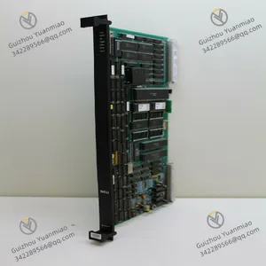
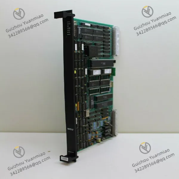
Metso Valmet A413015 Drive Board
Related Products
-
 Metso Valmet A413160 FIU1 Frequency Input BoardNegotiableMOQ: 1 Piece
 -
Metso Valmet A413115 Ver.04 TCU41 BoardNegotiableMOQ: 1 Piece
-
Metso Valmet A413091 GDU Control BoardNegotiableMOQ: 1 Piece
-
Metso Valmet A413050 RSU6 Serial Controller Unit ModuleNegotiableMOQ: 1 Piece
-
METSO DPU-MR Processing UnitNegotiableMOQ: 1 Unit
I. Overview
The Metso A413015 is an industrial-grade high-precision analog input/output module, mainly designed to be compatible with the control systems of Metso crushing and screening equipment (such as cone crushers, vibrating screens, heavy-duty feeders, etc.). It undertakes the core functions of "on-site analog sensor signal acquisition (e.g., pressure, temperature, liquid level) - signal amplification and filtering - standard signal output to actuators". Its design focuses on "signal acquisition accuracy" and "anti-interference capability" for heavy-duty industrial scenarios. It adopts high-precision ADC/DAC chips and a multi-layer electromagnetic shielding structure, which can effectively suppress mechanical vibrations, electromagnetic radiation, and dust interference in crushing workshops, ensuring stable transmission and accurate conversion of analog signals. It is widely used in industries with strict requirements for parameter monitoring accuracy, such as mining, building materials, and metallurgy.
Compared with general-purpose analog modules, this module features "in-depth compatibility with Metso equipment protocols", "wide-range signal adaptation", and "fault self-diagnosis". It can be directly integrated into Metso C100/C200 series control cabinets, enabling seamless connection with the crusher's main controller, high-precision sensors (e.g., pressure transmitters, temperature sensors), and actuators (e.g., proportional valves, frequency converters). This ensures the accurate regulation of key process parameters such as load adjustment and pressure control of crushing equipment.
II. Technical Parameters
Basic Specifications
2. Electrical Performance
Power Supply Parameters:
Analog Input Characteristics:
Analog Output Characteristics:
Communication Interface:
3. Environmental Adaptability Parameters
III. Functional Features
1. High-Precision Signal Processing and Multi-Type Adaptation
2. Anti-Interference Design for Heavy-Duty Industry
3. Convenient Operation & Maintenance and Fault Diagnosis
4. Exclusive Collaboration with Metso Equipment
IV. Common Faults and Troubleshooting Methods

Send Inquiry to This Supplier


You May Also Like
-
METSO IOP302 Control ModuleNegotiableMOQ: 1 Unit
-
METSO IOP304 Control ModuleNegotiableMOQ: 1 Unit
-
METSO IOP331 Intelligent Operations Platform ModuleNegotiableMOQ: 1 Unit
-
METSO IOP345 Digital Input ModuleNegotiableMOQ: 1 Unit
-
METSO PDP401 Distributed Processing UnitNegotiableMOQ: 1 Unit
-
METSO PDP601 Distributed Processing UnitNegotiableMOQ: 1 Unit
-
METSO D100644 ControllerNegotiableMOQ: 1 Unit
-
METSO IOP351 Relay Output ModuleNegotiableMOQ: 1 Unit
-
METSO A413084 Processor ModuleNegotiableMOQ: 1 Piece
-
Metso Valmet CPU A413044 PLC BoardNegotiableMOQ: 1 Piece


