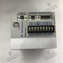
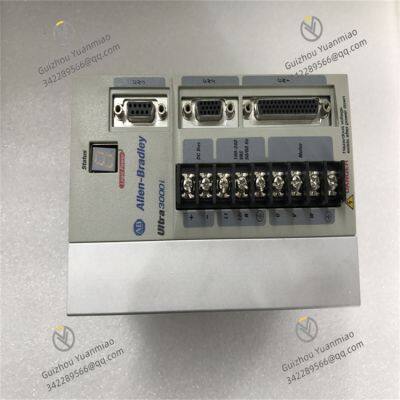
I. Product Overview
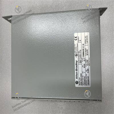
2098-DSD-020X is a digital servo drive in the Ultra 3000 motion control series under Allen-Bradley. It plays a key role in the field of industrial automation, providing stable and efficient driving solutions for various equipment that require precise motion control. With its excellent performance and reliable quality, this product is favored by industrial users. It is mainly used to connect with servo motors (such as Allen-Bradley's Kinetix servo motor series), and through precise control commands, realizes accurate motion and position control of the connected load, ensuring high precision and stability in the industrial production process.
II. Technical Parameters
(1) Power-related Parameters
Input Voltage: Supports single-phase input voltage of 100-240V AC rms, which can adapt to the power supply requirements in different industrial environments. It can work normally both in conventional production workshops with relatively stable voltage and in special industrial places with a certain range of voltage fluctuations, providing a basic guarantee for the stable operation of the drive.
Input Frequency: The input frequency range is 47-63Hz, which is compatible with common industrial AC frequencies. It can be adapted to different regions and different power supply conditions, enhancing the global versatility of the product.
Input Current: The nominal input current is 18A rms. This current specification ensures that the drive can stably obtain the required electric energy when connected to the industrial power supply, so as to support the normal operation of its internal circuits and control modules, and then provide stable driving energy for the motor.
Output Voltage and Frequency: The output voltage is 120/240V AC rms (three-phase). This three-phase output design can better drive three-phase servo motors, providing stable and efficient power output. The programmable range of output frequency is 0-400Hz. The output frequency can be flexibly adjusted according to the speed requirements of the motor in actual application scenarios, realizing precise control of the motor speed and meeting the operation requirements under different working conditions from low speed to high speed.
(2) Current and Power Parameters
Output Current: It has strong current output capability, with a continuous output current of up to 10A (0 peak). This means that under long-term stable operation, the drive can continuously provide 10A current for the motor to maintain stable operation of the motor. In special working conditions such as motor start-up, acceleration or short-term high load, it can also provide intermittent output current up to 30A (0 peak), meeting the motor's demand for instantaneous large current and ensuring that the motor can successfully cope with various complex working states.
Output Power: It performs well in terms of power output. When the input voltage is 115V AC, the continuous output power is 1.0kW; when the input voltage is increased to 230V AC, the continuous output power can reach 2.0kW. This characteristic of automatically adjusting the output power according to the input voltage enables the drive to provide appropriate power support for the motor under different power supply conditions, ensuring efficient operation of the equipment.
(3) Environmental Adaptability Parameters
Temperature Range: The operating temperature range is 0-55°C (32-131°F). Within this temperature range, the electronic components and circuits inside the drive can maintain good performance, ensuring stable operation of the equipment and adapting to the temperature conditions of most industrial production environments. In terms of storage, its tolerance temperature range is wider, -40-70°C (-40-158°F), which enables the product to effectively avoid damage caused by temperature problems during transportation, long-term storage and waiting for installation and use in some extreme temperature environments, greatly improving the applicability and reliability of the product.
Humidity Range: Whether in operation or storage, the drive can work normally in an environment with a relative humidity of 5%-95% (non-condensing). This feature enables it to adapt to industrial environments with various humidity conditions, whether in humid southern regions or relatively dry northern regions, it can operate stably without being affected by changes in environmental humidity, effectively reducing the risk of failures caused by humidity problems.
Altitude: During operation, the drive can work normally at an altitude of 1000 meters (3280 feet) and below without derating, which can meet the altitude requirements of most conventional industrial places. This parameter ensures the applicability of the product in different altitude areas, whether in factories in plain areas or industrial facilities in some inland areas with slightly higher altitudes, it can stably exert its performance advantages.
Vibration and Impact: The drive has good anti-vibration and anti-impact performance. In terms of vibration, it can maintain optimal function in a 2.5g vibration environment, which can effectively resist common vibration interference in industrial sites, ensure the stability of internal circuit connections and the accuracy of data transmission, and reduce equipment failures caused by vibration. In terms of impact, the operating impact is 15g (3 pulses, 11 milliseconds), and the non-operating impact is 30g (3 pulses, 11 milliseconds). This impact resistance enables the product to effectively protect internal precision components during transportation, installation and in some industrial environments where instantaneous impact may exist, maintaining the normal operation state of the equipment.
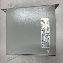
(4) Physical Specification Parameters
The size of the drive is 8 x 6 x 4 inches (200 x 145 x 98 mm). This compact design allows it to save a lot of space during installation, facilitating integration into various industrial equipment with limited space. At the same time, the small size does not affect its performance, realizing powerful motion control functions in a limited space. Its weight is 2.1 kg (4.6 lbs). The relatively light weight is not only convenient for transportation and installation, but also reduces the overall load of the equipment, which has significant advantages for some equipment designs with weight requirements.

III. Functional Features
(1) Integrated DeviceNet Communication Interface
2098-DSD-020X is equipped with an integrated DeviceNet communication interface, which enables it to directly communicate with controllers with DeviceNet function, such as Allen-Bradley's own SLC and Logix controllers. Through this communication interface, the drive can exchange data at a high rate and realize long-distance communication connections. This means that in the industrial automation system, it can quickly receive various control commands from the controller, such as motor start, stop, speed adjustment, position positioning and other commands, and timely feedback the drive's own operating status information (such as the motor's actual speed, current, temperature, etc.) to the controller, realizing centralized control and remote monitoring of the equipment. This efficient communication capability greatly improves the response speed and operating efficiency of the entire automation system, reduces the complexity of system wiring, and enhances the reliability and maintainability of the system.
(2) Built-in Indexing Function
The drive supports stepping function and has built-in indexing capability. Through this function, users can store pre-configured servo motor motion patterns in the drive's memory. These pre-configured motion patterns can include motor acceleration and deceleration processes, precise position positioning data and other motion-related parameter settings. In the actual production process, for different loads or product types, users can conveniently and quickly select the corresponding predefined indexing patterns from the drive, so that the servo motor can perform precise motion according to the preset path and parameters. For example, in the automated assembly production line, for the assembly of parts of different models of products, the corresponding motor motion patterns for each product can be set in advance. When producing different products, only the corresponding indexing patterns need to be called to realize precise control of the motor, which greatly improves the flexibility and efficiency of the production process and reduces the time cost and error risk caused by frequent adjustment of motor control parameters.
(3) Rich Feedback Control Support
2098-DSD-020X can accept feedback position data from a variety of encoders, including Allen-Bradley's sine/cosine encoders, and incremental external encoder data from announcements 842HR, 844D, 847H and 847T. By obtaining the actual position information of the motor fed back by these encoders, the drive can adjust the control strategy in real time and perform precise closed-loop control on the position of the servo motor. This precise position control capability is crucial in industrial application scenarios with extremely high position accuracy requirements, such as precision machining machine tools and semiconductor manufacturing equipment. By constantly comparing the target position with the actual feedback position, the drive can timely correct the motor's operation deviation, ensure that the motor drives the load to accurately reach the specified position, and effectively improve the processing accuracy and production quality of products.
IV. Common Faults and Solutions
(1) Power Fault
Fault Phenomenon: The drive cannot start normally, the power indicator is not on or flashes abnormally, and may be accompanied by abnormal heating or peculiar smell.
Possible Causes:
The input power voltage is beyond the normal range of 100-240V AC rms. Too high or too low voltage may cause the drive to fail to work normally. For example, power supply line faults and abnormal transformer output may cause abnormal input voltage.
There are short-circuit or open-circuit problems in the power line, such as broken or short-circuited internal wires of the power cord, poor contact of the plug, etc., which affect the normal supply of power.
The power conversion circuit inside the drive fails, such as damaged rectifier bridge, invalid filter capacitor, faulty voltage regulator chip, etc., which cannot convert the input power into a suitable working voltage to provide stable power support for other circuits inside the drive.
Solutions:
Use professional tools such as a multimeter to measure the input power voltage to ensure it is within the specified range. If the voltage is abnormal, check the upstream power supply equipment, such as distribution boxes and transformers, and repair or replace the faulty power supply equipment. For large voltage fluctuations, consider installing a voltage stabilizer to ensure the stability of the input voltage.
Carefully check the power line for obvious signs of damage or short circuit. For open-circuit problems, find the breakpoint through section-by-section inspection and repair it. Check the plug, socket and other connection parts to ensure firm connection. If there is poor contact, clean the interface or replace the plug and socket.
If it is suspected that there is a fault in the internal power circuit of the drive, it needs to be repaired by professional technicians. Generally, professional electronic testing equipment, such as oscilloscopes and logic analyzers, are needed to detect the components in the power circuit, find out the damaged components and replace them. When replacing components, select high-quality products with the same parameters as the original components to ensure the normal operation of the power circuit.
(2) Communication Fault
Fault Phenomenon: A stable communication connection cannot be established between the drive and the controller, the communication indicator shows abnormalities, and data transmission interruptions, delays or errors may occur, causing the drive to fail to receive correct control commands or feed back its own operating status information to the controller.
Possible Causes:
Loose or damaged communication line connections, such as poor contact of DeviceNet communication cable interfaces, short circuits or open circuits of internal wires caused by damaged cable sheaths, etc. In industrial sites, communication lines are prone to such problems due to equipment vibration, frequent movement, etc.
Incorrect communication parameter settings, including inconsistent settings of communication baud rate, node address, communication protocol, etc. between the drive and the controller, resulting in failure of normal communication between them. In addition, communication interference from other devices in the network may also affect the communication stability between the drive and the controller.
The communication module of the drive or controller fails, such as damaged communication chips, loose solder joints on the circuit board, etc., resulting in abnormal communication functions.
Solutions:
Check the communication line connection, re-plug the DeviceNet communication cable to ensure a firm interface. If the cable is damaged, replace it with a new communication cable in time. When wiring, pay attention to avoid parallel laying of communication cables and high-voltage cables to reduce electromagnetic interference. For longer communication lines, consider using shielded cables and take good grounding measures.
Carefully check the communication parameter settings of the drive and the controller to ensure they are consistent. Refer to the user manual of the equipment to correctly set parameters such as communication baud rate and node address. At the same time, use network detection tools, such as network analyzers, to detect whether there are communication interference sources in the network, and take corresponding measures to eliminate interference, such as adjusting equipment layout and increasing shielding measures.
If a hardware fault of the communication module is suspected, contact professional maintenance personnel to inspect and repair the communication modules of the drive and the controller. For damaged communication chips or circuit boards, replace them with new modules in time. After replacing the module, re-conduct communication tests to ensure that the communication function returns to normal.
(3) Abnormal Motor Operation
Fault Phenomenon: The motor cannot start, the speed is unstable, jitter or abnormal noise occurs during operation, or the motor running speed does not match the set value.
Possible Causes:
The motor itself fails, such as winding short circuit, open circuit, bearing damage, rotor eccentricity, etc. The motor runs in harsh working environments for a long time, such as high temperature, high humidity, and heavy dust, which easily leads to damage to internal components of the motor.
The output current or voltage of the drive is abnormal, unable to provide normal driving energy for the motor. This may be caused by damage to the internal power module of the drive, failure of the current detection circuit, abnormality of the voltage regulation circuit, etc.
Unreasonable control parameter settings, such as improper setting of PID parameters of the speed loop and position loop, resulting in reduced control performance of the motor. In addition, if the motor load is too large, exceeding the rated load capacity of the drive and the motor, it will also cause abnormal motor operation.
Solutions:
Conduct a comprehensive inspection of the motor, use an insulation resistance tester to detect the insulation resistance of the motor windings, and judge whether there is a winding short circuit or open circuit problem. Check the operation of the motor bearing, and replace the bearing in time if it is damaged. For problems such as rotor eccentricity, professional motor maintenance equipment can be used for repair or replace the motor rotor.
Check the output current and voltage of the drive, and use tools such as an oscilloscope to monitor the output waveform of the drive to judge whether there is an abnormality. If the internal power module of the drive is damaged, it needs to be replaced by professional technicians. At the same time, check the components in the current detection circuit and voltage regulation circuit, and replace the corresponding components in time if they are damaged.
Readjust the control parameters of the drive, and reasonably set the PID parameters of the speed loop and position loop according to the motor model and load characteristics to optimize the control performance of the motor. For the case of excessive motor load, check whether there are jamming, blockage and other problems in the mechanical transmission part, clean up the debris in the transmission parts, repair or replace the damaged mechanical parts to reduce the motor load. If the load really exceeds the rated capacity of the drive and the motor, consider replacing the drive and motor with higher power.
(4) Overheating Fault
Fault Phenomenon: The surface temperature of the drive is too high, with a Obvious hot feeling when touched, the overheating indicator light is on, which may cause the drive to automatically shut down for protection to avoid damage to internal components due to overheating.
Possible Causes:
The working environment temperature is too high, exceeding the normal working range of 0-55°C, causing difficulty in heat dissipation of the drive. For example, in some industrial workshops without good ventilation facilities or during high-temperature periods in summer, the ambient temperature is prone to rise, affecting the heat dissipation effect of the drive.
The heat dissipation channel of the drive is blocked by dust and debris, affecting heat dissipation. When used in a dusty environment for a long time, dust will gradually accumulate on the heat sink, fan and other heat dissipation components of the drive, reducing heat dissipation efficiency. In addition, failures of the cooling fan, such as damaged fan blades and burned motor, will also lead to poor heat dissipation.
There are faults such as component short circuits or overloads inside the drive, resulting in increased power consumption and excessive heat generation. For example, a breakdown and short circuit of an IGBT tube in the power module, or an abnormality in the control circuit of the drive, causing some components to be in a high-load working state for a long time, will cause the drive to overheat.
Solutions:
Improve the working environment and strengthen ventilation and heat dissipation measures. Air conditioners, fans and other equipment can be installed to reduce the ambient temperature and ensure that the working environment temperature of the drive is normal