

Home > Electrical & Electronics > Electrical Control System > GE 151X1233DB02SA02 Digital Input Module


Negotiable
MOQ: 1 Piece (Price negotiable depending on order volume and customization)
Key Specifications
Get Latest Price
Material:
Other
Certification:
Other
Function:
Other
Payment & Shipping
Payment Methods:
Port of Shipment:
China
Delivery Detail:
Delivery time depends on order quantity.
Related Products
-
 GE 151X1225DF01PC01R3 Digital Input ModuleNegotiableMOQ: 1 Piece
 -
GE IS200ESERLH3AAA Excitation Control System ModuleNegotiableMOQ: 1 Piece
-
GE 151X1207BB55SA01 VersaMax Series Industrial Control ModuleNegotiableMOQ: 1 Piece
-
8521-HC-MT PAC8000 Series Hybrid ControllerNegotiableMOQ: 1 Piece
-
DS200TCQAG1BHF Digital Input/Output (I/O) ModuleNegotiableMOQ: 1 Piece
Material
Other
Certification
Other
Function
Other
Condition
Other
Task
Other
Mathematical Model
Other
Signal
Other
Customized
Other
Structure
Other
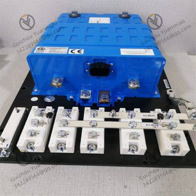
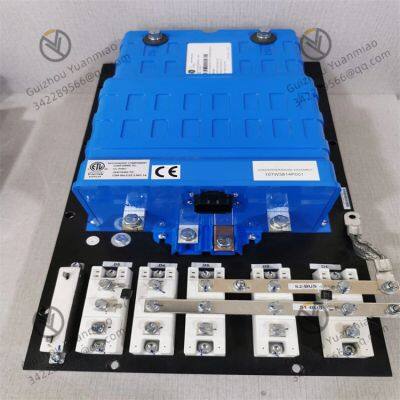
GE 151X1233DB02SA02 Digital Input Module
The working principle of the GE 151X1233DB02SA02 digital input module is based on the collaborative operation of signal acquisition, electrical isolation, level conversion, and status transmission. Its core is to convert the switching signals of external devices (such as the on-off status of sensors and buttons) into logic signals (0/1 status) recognizable by controllers like PLCs, while ensuring the safety and anti-interference performance of signal transmission. The specific working principle is as follows:
- External Signal Access: Receiving Switching Signals
This design facilitates on-site engineers to quickly troubleshoot problems such as wiring errors and signal loss.

Send Inquiry to This Supplier

* Email
Want the best price?
Post an RFQ now!

1Yr
Business Type
Trading Company
Year Established
2014
Factory Size
1,000-3,000 square meters
Product Certifications
SA8000
You May Also Like
-
IC660BBA104 Hybrid I/O ModuleNegotiableMOQ: 1 Piece
-
IC693CPU372-AE Programmable Logic ControllerNegotiableMOQ: 1 Piece
-
IC693CPU374 Performance Single Slot CPU ModuleNegotiableMOQ: 1 Piece
-
IC693DNM200 Digital ModuleNegotiableMOQ: 1 Piece
-
IC693MDL240 Digital Output ModuleNegotiableMOQ: 1 Piece
-
IC693PWR322F PLC Power ModuleNegotiableMOQ: 1 Piece
-
IC693PWR330 Power ModuleNegotiableMOQ: 1 Piece
-
IC695CHS012 12 Slot Universal SubstrateNegotiableMOQ: 1 Piece
-
IC695CPE310-ACAT CPU ModuleNegotiableMOQ: 1 Piece
-
IC695PSD040-F Power Modules in the RX3i SeriesNegotiableMOQ: 1 Piece


