

Home > Electrical & Electronics > Electrical Control System > GE 151X1225DF01PC01R3 Digital Input Module

Negotiable
MOQ: 1 Piece (Price negotiable depending on order volume and customization)
Key Specifications
Get Latest Price
Material:
Other
Certification:
Other
Function:
Other
Payment & Shipping
Payment Methods:
Port of Shipment:
China
Delivery Detail:
Delivery time depends on order quantity.
Related Products
-
 GE IS200ESERLH3AAA Excitation Control System ModuleNegotiableMOQ: 1 Piece
 -
GE 151X1207BB55SA01 VersaMax Series Industrial Control ModuleNegotiableMOQ: 1 Piece
-
8521-HC-MT PAC8000 Series Hybrid ControllerNegotiableMOQ: 1 Piece
-
DS200TCQAG1BHF Digital Input/Output (I/O) ModuleNegotiableMOQ: 1 Piece
-
IC660BBA104 Hybrid I/O ModuleNegotiableMOQ: 1 Piece
Material
Other
Certification
Other
Function
Other
Condition
Other
Task
Other
Mathematical Model
Other
Signal
Other
Customized
Other
Structure
Other
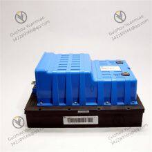
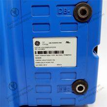
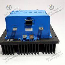
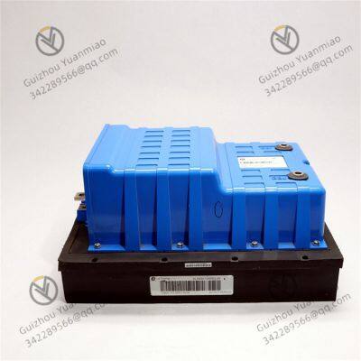
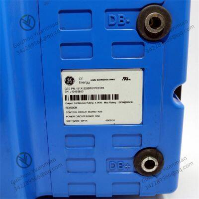
GE 151X1225DF01PC01R3 Digital Input Module

Send Inquiry to This Supplier

* Email
Want the best price?
Post an RFQ now!

1Yr
Business Type
Trading Company
Year Established
2014
Factory Size
1,000-3,000 square meters
Product Certifications
SA8000
You May Also Like
-
IC693CPU372-AE Programmable Logic ControllerNegotiableMOQ: 1 Piece
-
IC693CPU374 Performance Single Slot CPU ModuleNegotiableMOQ: 1 Piece
-
IC693DNM200 Digital ModuleNegotiableMOQ: 1 Piece
-
IC693MDL240 Digital Output ModuleNegotiableMOQ: 1 Piece
-
IC693PWR322F PLC Power ModuleNegotiableMOQ: 1 Piece
-
IC693PWR330 Power ModuleNegotiableMOQ: 1 Piece
-
IC695CHS012 12 Slot Universal SubstrateNegotiableMOQ: 1 Piece
-
IC695CPE310-ACAT CPU ModuleNegotiableMOQ: 1 Piece
-
IC695PSD040-F Power Modules in the RX3i SeriesNegotiableMOQ: 1 Piece
-
IC695RMX128 Redundant Memory Swapping ModuleNegotiableMOQ: 1 Piece


