Home > Electrical & Electronics > Electrical Control System > ALSTOM MLU VER.A01 DCS System Module Card

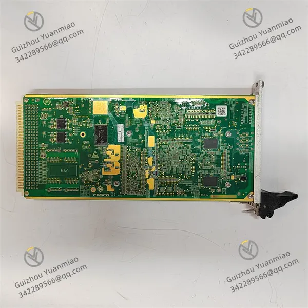
ALSTOM MLU VER.A01 DCS System Module Card
ALSTOM MLU VER.A01 DCS System Module Card photo-1
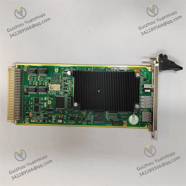
ALSTOM MLU VER.A01 DCS System Module Card photo-2
Negotiable MOQ: 1 Piece (Price negotiable depending on order volume and customization)
Key Specifications
Get Latest Price
Material:
Other, Global universal model
Condition:
Other, Global universal model
Task:
Other, Global universal model

Payment & Shipping
Payment Methods:
Port of Shipment:
China
Delivery Detail:
Delivery time depends on order quantity.
Material Other, Global universal model
Condition Other, Global universal model
Task Other, Global universal model
Mathematical Model Other, Global universal model
Signal Other, Global universal model
Customized Non-Customized
Structure Other, Global universal model
Working voltage 220V
Output frequency 60kHz
ALSTOM MLU VER.A01
Functional Features
  • Data Acquisition and Monitoring:Capable of collecting data from sensors, instruments, and other devices, and performing real-time monitoring and reporting to provide a basis for judging the operational status of the system.

  • Signal Conversion and Processing:Converts different types of signals to meet system requirements, ensuring signal compatibility and normal communication among devices.

  • Control Execution:Receives instructions from the control system and executes corresponding operations, such as controlling valve opening/closing and adjusting motor speed, to achieve precise control of industrial equipment.

  • Network Communication:Equipped with Ethernet, serial, and bus communication interfaces to connect and communicate with other devices and systems, enabling data sharing and exchange for system integration and collaborative operation.

  • Library Management Function:Automatically includes IEC libraries with functions, function blocks, and data types. These library elements can be used for project replication, and some can be modified. Additionally, project element libraries created in other TriStation ALSTOM MLU VER.A01 projects can be added to facilitate users in updating library content and enriching project resources.

Functional Characteristics
  • Features data acquisition and monitoring to collect and report data from sensors and other devices in real time.

  • Enables signal conversion and processing to adapt to system requirements.

  • Receives control system instructions to execute operations like valve switching and motor speed control.

  • Equipped with Ethernet, serial, and bus communication interfaces to communicate with other devices for data sharing and exchange.

ALSTOM MLU VER

Working PrincipleI. Core Control Architecture and Data Processing Flow
  1. Signal Acquisition and Input Processing
  • Multi-type Signal Access:Collects real-time data from field sensors (temperature, pressure, flow, etc.), actuators, or instruments through built-in I/O interfaces (such as analog and digital input ports). For example, it receives analog temperature signals (0-10V or 4-20mA) from thermocouples or pulse digital signals from encoders.

  • Signal Conditioning and Conversion:After preprocessing such as filtering, amplification, and isolation, input signals are converted into digital signals recognizable by the module via A/D converters (analog) or level conversion circuits (digital). For instance, a 4-20mA current signal is converted into a 0-100% engineering quantity value.

  • Logical Operation and Program Execution
    • Built-in Processor Calculation:The CPU (e.g., 32-bit microprocessor) of the module performs real-time calculations on input data based on preset control programs (written in languages such as ladder logic and function block diagrams). For example, it compares temperature sensor data with set thresholds to determine whether to trigger alarms or control instructions.

    • IEC Standard Library Support:Relying on the built-in IEC 61131-3 standard library (including functions, function blocks, and data types), it realizes functions such as logical control, mathematical operations, and PID regulation. For example, a PID function block is called to perform closed-loop control on flow signals and output instructions to adjust valve opening.

  • Control Output and Equipment Drive
    • Signal Conversion and Output:Operation results are converted into physical signals via D/A converters (analog) or relays/transistors (digital) to drive external devices. For example, it outputs a 4-20mA current signal to control the opening of a regulating valve or outputs switching signals to start/stop a motor.

    • Real-time Response Mechanism:The module uses a scanning cycle mechanism (e.g., 10ms-100ms) to cyclically execute the "acquisition-calculation-output" process, ensuring the real-time nature of control actions, suitable for rapidly changing industrial scenarios (such as production line speed adjustment).

    II. Communication and System Integration Principle
    1. Multi-protocol Communication Interfaces
    • Ethernet Interface:Supports protocols like Modbus TCP and EtherNet/IP through RJ45 ports to interact with upper-level computers (SCADA systems) or PLCs. For example, it uploads device operation status to the monitoring system and receives remote parameter modification instructions.

    • Serial and Bus Interfaces:Supports protocols like Modbus RTU and CANopen through RS-232/485 ports to connect distributed I/O modules or field instruments. For instance, it obtains the speed data of frequency converters via the CAN bus to achieve collaborative control of multiple devices.

    • Communication Data Processing:The built-in communication protocol stack parses and encapsulates received data, supporting data caching and error checking (such as CRC checking) to ensure communication reliability.

  • Distributed System Collaboration Mechanism
    • Master-Slave Communication Mode:As a slave module of the DCS system, it communicates with the master controller via the bus (such as Profibus DP) to receive control instructions and feedback status. For example, in a power plant DCS system, it receives instructions from the main control unit to adjust the coal feeding amount of the coal feeder.

    • Data Synchronization and Redundancy:If the system has a redundant design, the module can synchronize data in real time with the standby module through a hot standby link, and automatically switch when the main module fails to avoid control interruption (such as a dual CPU redundant architecture).

    ALSTOM MLU VER

    III. Protection and Self-diagnosis Mechanism
    1. Hardware Protection Design
    • Electrical Protection:Input/output ports are equipped with overvoltage and overcurrent protection circuits (such as TVS tubes and current limiting resistors) to prevent damage to the module caused by field device failures (such as short circuits). For example, when the input voltage exceeds 24V±10%, the protection circuit automatically cuts off the signal path.

    • Anti-interference Design:Measures such as optoelectronic isolation and metal shielding casings are adopted to suppress electromagnetic interference (EMI) and radio frequency interference (RFI), ensuring stable operation in industrial environments (such as near frequency converters).

  • Self-diagnosis and Fault Feedback
    • Status Monitoring:Built-in watchdog timer, temperature sensor, etc., to monitor CPU operation status, module temperature, power voltage, etc., in real time. For example, when the temperature exceeds 70℃, it triggers a overheat alarm and reduces the operation frequency.

    • Fault Code Output:Outputs fault codes (such as "E01" for communication timeout) through LED indicators (such as power, operation, and fault lights) or communication interfaces to help maintenance personnel quickly locate problems.

    IV. Programming and Project Management Principle
    1. Software Development Environment
    • Programming Tool Support:Uses special software such as ALSTOM TriStation for program development, supporting IEC 61131-3 standard programming languages (ladder diagram, structured text, etc.). For example, interlock logic for motor start/stop is written through ladder diagrams.

    • Library File Calling:Built-in function libraries (such as mathematical operations and communication protocol function blocks) can be called directly, and users can also customize function blocks and add them to the project library to improve programming efficiency (such as creating a dedicated PID regulation function block).

  • Project Deployment and Update
    • Download and Debugging:Programs are downloaded to the module via USB or Ethernet, supporting online debugging (such as forcing I/O status and monitoring variable values) to facilitate on-site parameter optimization.

    • Version Management:Supports project version control, allowing replication of existing project library elements or import of custom modules from other projects to adapt to rapid configuration in different industrial scenarios (such as reusing part of the logic for chemical reactor and boiler control projects).

    V. Application Scenario Adaptation Principle
    1. Industrial Automation Control
    • Process Control:In chemical production lines, it collects temperature and pressure signals from reaction kettles and adjusts the opening of feed valves through PID algorithms to maintain stable reaction conditions.

    • Sequence Control:In metallurgical rolling mill systems, it controls the start/stop and speed switching of rolling mill motors in a preset sequence based on sensor signals to realize the automation of the steel rolling process.

  • Power System Monitoring
    • Substation Automation:Collects signals such as transformer oil temperature and switch status, uploads them to the power monitoring system via Ethernet, and outputs tripping instructions to circuit breakers in case of anomalies.

    • New Energy Control:In photovoltaic power stations, it monitors the output power of each inverter and coordinates the active/reactive power adjustment of grid-connected inverters via the bus to optimize power quality.

    Conclusion
    ALSTOM MLU VER.A01 realizes precise control and system integration of industrial equipment through a closed-loop architecture of "signal acquisition-logical operation-control output-communication interaction-self-diagnosis", combined with the IEC standard programming system and multi-protocol communication capabilities. Its design balances real-time performance, reliability, and flexibility, making it suitable for industrial scenarios requiring distributed control and complex logic processing.
    Product Tags: MLU VER.A01

    Send Inquiry to This Supplier

    * Message
    0/5000

    Want the best price? Post an RFQ now!
    Verified Business License
    Business Type
    Trading Company
    Year Established
    2014
    Factory Size
    1,000-3,000 square meters
    Product Certifications
    SA8000