Home > Electrical & Electronics > Electrical Control System > Honeywell CC-PDIL01 51405040-175 Digital Input Module

Honeywell CC-PDIL01 51405040-175 Digital Input Module
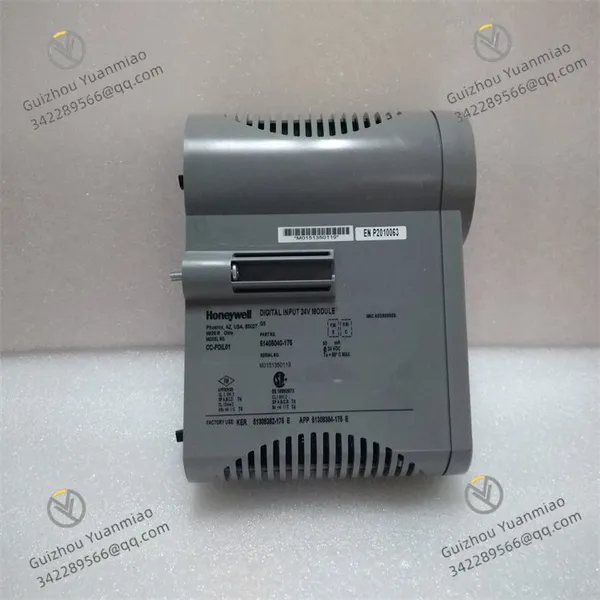
Honeywell CC-PDIL01 51405040-175 Digital Input Module photo-1
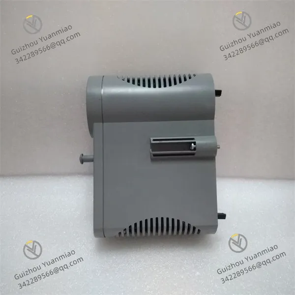
Honeywell CC-PDIL01 51405040-175 Digital Input Module photo-2
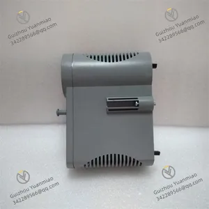
Honeywell CC-PDIL01 51405040-175 Digital Input Module photo-3
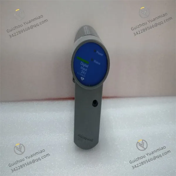
Negotiable MOQ: 1 Piece (Price negotiable depending on order volume and customization)
Key Specifications
Get Latest Price
Material:
Other, Global universal model
Condition:
Other, Global universal model
Task:
Other, Global universal model

Payment & Shipping
Payment Methods:
Port of Shipment:
China
Delivery Detail:
Delivery time depends on order quantity.
Material Other, Global universal model
Condition Other, Global universal model
Task Other, Global universal model
Mathematical Model Other, Global universal model
Signal Other, Global universal model
Customized Non-Customized
Structure Other, Global universal model
Honeywell CC-PDIL01
Functional Features
  • Signal Processing
    Designed to connect digital devices and sensors, it receives binary or digital signals from field devices and processes them within the control system. This is crucial for applications requiring monitoring and handling of discrete on/off signals.
  • Independent Channel Monitoring
    Typically equipped with 32 digital input channels. Each channel can independently monitor digital signals, allowing connection to multiple field devices.
  • Electrical Isolation
    Using optoelectronic isolation technology, each input channel is electrically isolated from other channels and the common terminal, with an isolation voltage of 1500V AC rms or ±1500V DC. This prevents noise and interference from affecting each other between channels.
Technical Parameters
  • Input Channels: 32 channels.

  • Power Voltage Range: 18-30V DC.

  • On-Detection Voltage/Current: Minimum 13V DC or 3mA.

  • Off-Detection Voltage/Current: Maximum 5V DC or 1.2mA.

  • Input Impedance: 4.2kΩ.

  • Absolute Delay: 5ms±20% after input filtering and isolation.

  • Field Resistance for Guaranteed On Condition: Maximum 300Ω at 15V DC.

  • Field Resistance for Guaranteed Off Condition: Minimum 30kΩ at 30V DC.

Working Principle
The CC-PDIL01 module connects to field digital devices or sensors via its input channels. When field devices send binary signals (high or low level), the module collects and processes these signals. The internal circuit converts input electrical signals into digital signals, and optoelectronic isolation technology ensures signal stability and security, preventing external electrical interference from affecting the module and control system. The converted digital signals are transmitted to the control system's processor for further logic operations, monitoring, and control, enabling real-time monitoring and control of various discrete states in industrial processes.

CC-PDIL01 51405040-175 (3)

CC-PDIL01 51405040-175 (1)

Troubleshooting Guide for Honeywell CC-PDIL01 Module1. Power Issue Inspection
  • Check Supply Voltage
    Ensure the input power voltage to the module is 24V DC, allowing a certain voltage fluctuation range without exceeding the specified value. Use a multimeter to measure the voltage at the power output terminal for normal range.
  • Check Power Indicator
    The module typically has a power indicator light. Observe if it is on. If the indicator is off, check for loose power connections, damaged power cables, or whether the power switch is turned on.
  • Verify Power Redundancy
    If the system uses redundant power configuration, check the working status of the redundant power supply to ensure one supply can work normally when the other fails. Refer to relevant manuals for redundant power testing.
2. Input Signal Troubleshooting
  • Check Input Signal Status
    Use a multimeter or other testing tools to verify if the voltage or current value of the input signal meets the module's requirements. For example, the "on" state voltage range of the CC-PDIL01 module is typically 18-30V DC, and the "off" state voltage should be less than 5V DC.
  • Inspect Input Indicators
    The module usually has indicators corresponding to each input channel. Check if the indicators light up or go off correctly according to the input signal status. If an indicator for a channel does not light up or flashes abnormally, the input signal for that channel may be faulty, or the channel itself may be damaged.
  • Examine Input Wiring
    Check if the connection wiring from the signal source to the module's input terminals is intact, with no open circuits, short circuits, or poor contacts. Use a cable tester to check the continuity of network cables or other connection wires, and re-plug the connection terminals to ensure firm connections.
  • Test Signal Source
    If the module and wiring are confirmed to be problem-free, check if the signal source (such as sensors, switches, etc.) is working normally. Test by replacing the signal source with the same model, or check if the signal source's output meets its specification requirements.
3. Module Diagnosis and Alarm Information Review
  • Utilize Module Self-Diagnosis Function
    The CC-PDIL01 module has an internal diagnosis function. View the module's diagnostic information through relevant software tools or the diagnostic interface on the module to check for error codes or fault prompts. Refer to the prompt information to find the corresponding fault cause and solution.
  • Check System Alarm Information
    In the entire control system, review alarm information related to the CC-PDIL01 module. Such information may provide more detailed fault descriptions and locations, helping to quickly locate issues.
4. Communication Issue Handling
  • Inspect Communication Interface
    If the module communicates with other devices via a certain communication protocol, check if the communication interface is working normally. Verify if the interface connection is loose and if the interface indicator lights normally display the communication status.
  • Confirm Communication Parameter Settings
    Ensure the module's communication parameters (such as baud rate, data bits, stop bits, parity bits, etc.) match the settings of other communication devices. Incorrect parameter settings will lead to communication failure.
  • Verify Communication Protocol Compatibility
    Confirm that the used communication protocol is supported by both the module and the communicating device, and that the protocol versions of both parties are compatible.
5. Environmental Factor Check
  • Check Temperature and Humidity
    The module's operating temperature range is generally -20°C to +60°C, and the relative humidity range is 5% to 95%. Ensure the environment where the module is located falls within the specified range to avoid performance degradation or failure due to environmental factors.
  • Investigate Electromagnetic Interference (EMI)
    Strong EMI may exist in industrial environments, which can affect the module's normal operation. Check if the module is installed away from EMI sources such as large motors and transformers, and ensure the module is well-grounded to reduce EMI impact.
6. Hardware Fault Troubleshooting
  • Inspect Module Appearance
    Check if the module's casing is damaged, deformed, or overheated. Examine the electronic components on the module for signs of burning, leakage, or other abnormalities. If obvious hardware damage is found, replace the module.
  • Attempt Module Replacement
    If the fault cause cannot be determined after the above checks, try replacing the CC-PDIL01 module with a new one to confirm if the original module has hardware faults. When replacing the module, follow the correct installation steps and ensure the new module's model and configuration match the original.
Product Tags: CC-PDIL01 , 51405040-175 , CC-PDIS01

Send Inquiry to This Supplier

* Message
0/5000

Want the best price? Post an RFQ now!
Verified Business License
Business Type
Trading Company
Year Established
2014
Factory Size
1,000-3,000 square meters
Product Certifications
SA8000