

Home > Electrical & Electronics > Electrical Control System > ABB Bailey INIIT13 Infi to Infi-Net Local Transfer
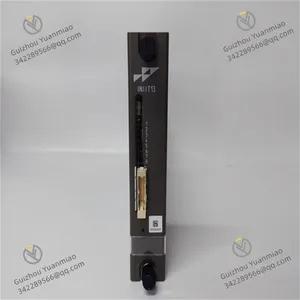
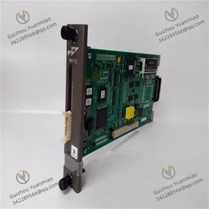
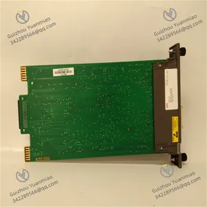
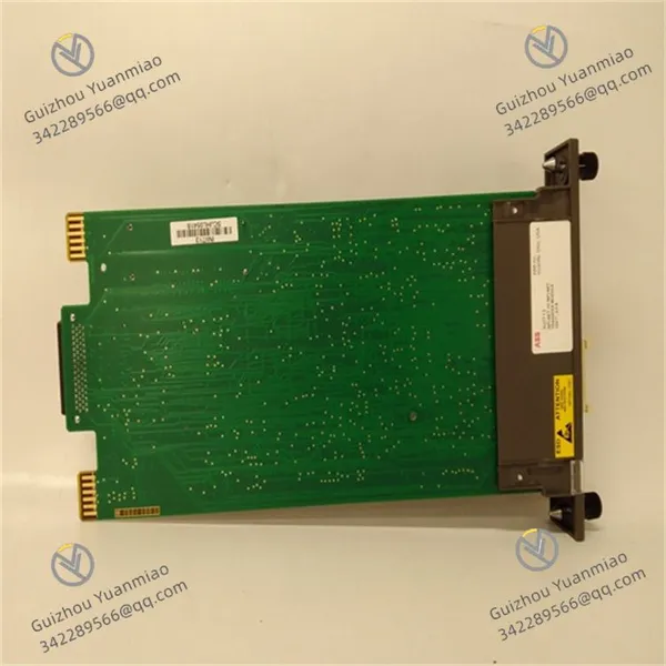
ABB Bailey INIIT13 Infi to Infi-Net Local Transfer


Negotiable
MOQ: 1 Piece (Price negotiable depending on order volume and customization)
Key Specifications
Get Latest Price
Material:
Other, Global universal model
Condition:
Other, Global universal model
Task:
Other, Global universal model
Payment & Shipping
Payment Methods:
Port of Shipment:
China
Delivery Detail:
Delivery time depends on order quantity.
Related Products
-
 ABB Bailey IMFCS01 Frequency Counter Slave ModuleNegotiableMOQ: 1 Piece
 -
ABB KUC720AE01 3BHB000652R0001 Control BoardNegotiableMOQ: 1 Piece
-
ABB KUC755AE106 3BHB005243R0106 Power Exciter Control ModuleNegotiableMOQ: 1 Piece
-
ABB KUC711AE101 3BHB004661R0101 Gate Unit Power SupplyNegotiableMOQ: 1 Piece
-
ABB KUC321AE HIEE300698R0001 ControllerNegotiableMOQ: 1 Piece
Material
Other, Global universal model
Condition
Other, Global universal model
Task
Other, Global universal model
Mathematical Model
Other, Global universal model
Signal
Other, Global universal model
Customized
Non-Customized
Structure
Other, Global universal model
Operating Voltage
DC 24V (±10%)
Communication Rate
1200bps~115.2kbps
Operating Temperature
-20℃ ~ +60℃
ABB Bailey INIIT13I. Basic OverviewII. Functional FeaturesCommunication Protocol SupportInterface and Electrical CharacteristicsData Processing and Real-Time PerformanceDiagnosis and Safety Design

Send Inquiry to This Supplier

* Email
Want the best price?
Post an RFQ now!

1Yr
Business Type
Trading Company
Year Established
2014
Factory Size
1,000-3,000 square meters
Product Certifications
SA8000
You May Also Like
-
ABB SM811K01 3BSE018173R1 Safety CPU ModuleNegotiableMOQ: 1 Piece
-
ABB LD800HSE 3BDH000320R0101 Foundation Fieldbus Linking DeviceNegotiableMOQ: 1 Piece
-
ABB UFC760BE145 3BHE004573R0145 Interface BoardNegotiableMOQ: 1 Piece
-
ABB 500AIM02 1HDF 930412 X010 Controller ModuleNegotiableMOQ: 1 Piece
-
ABB 500BIM01 1MRB150024R0002 Baseplate I/O ModuleNegotiableMOQ: 1 Piece
-
ABB 500BIO01 1MRB200060/E Digital I/O ModuleNegotiableMOQ: 1 Piece
-
ABB 500BOM01 1MRB150023R0002 Communication Mother BoardNegotiableMOQ: 1 Piece
-
ABB 500CMP04 HE401314/0001 Power Supply ModuleNegotiableMOQ: 1 Piece
-
ABB 500CPU03 1HDF700003R5122 CPU ModuleNegotiableMOQ: 1 Piece
-
ABB 500CSP04 HE401314/0002 Communication ProcessorNegotiableMOQ: 1 Piece


