

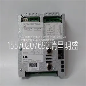
Module Spare Parts HVC-02B 3HNA024966-00103

Related Products
-
 Module Spare Parts IC3645LXCD1TTUS$ 1 - 100000MOQ: 1 Piece
 -
Module Spare PartsIC690RFH008US$ 1 - 100000MOQ: 1 Piece
-
Module Spare Parts PPC322BE HIEE300900R1US$ 1 - 100000MOQ: 1 Piece
-
Module Spare PartsPPC380AE01 HIEE300885R1US$ 1 - 100000MOQ: 1 Piece
-
Module Spare Parts PPC380AE102US$ 1 - 100000MOQ: 1 Piece
Focus on DCS, PLC, robot control system and large servo system.
Main products: various modules / cards, controllers, touch screens, servo drivers.
Advantages: supply of imported original products, professional production parts,
Fast delivery, accurate delivery time,
The main brands include ABB Bailey, Ge / fuanc, Foxboro, Invensys Triconex, Bently, A-B Rockwell, Emerson, ovation, Motorola, xyvom, Honeywell, Rexroth, KUKA, Ni, Deif, Yokogawa, Woodward, Ryan, Schneider, Yaskawa, Moog, prosoft and other brands
| HVC-02B 3HNA024966-00103 |
The adapter replaces the optional ACS100-PAN control panel. To eliminate the stress caused by the cables, use a strain relief. Selecting the Communication Speed Communication speed is selected by DIP switch S1 and by parameter 5201 COMM SPEED. The factory setting for the communication speed is 9600 bps (bits per second). Communication speed setting using DIP switch S1 is needed only when the adapter operates in RS485 mode. Figure 2 Selecting the communication speed for the adapter. DIP switch S1 Communication speed 300 bps 600 bps 1200 bps 2400 bps 4800 bps 9600 bps 19200 bps ON ON ON ON ON ON ON 5 INSTALLATION Selecting RS485 or RS232 Mode The adapter operates either in RS232 mode or in RS485 mode, selectable by a jumper. As a factory setting, the adapter operates in RS485 mode. Figure 3 Selecting the operating mode. RS485 Bus Termination The RS485 bus must be terminated using 120 Ω resistors at both ends of the network. The adapter has built-in termination resistors that can be enabled by jumpers S2 and S3. Refer to “Earthing and Termination” on page 10. By default, bus termination is enabled. Figure 4 Selecting RS485 termination impedance. Jumper S5 Mode RS485 RS232 1 2 S5 S2 S3 Jumper S2 Jumper S3 Both jumpers S2 and S3 must be connected in order to obtain 120 Ω. If no termination is needed, both jumpers S2 and S3 must be opened. 6 Installation to RS485 Bus 1 Make sure power is not connected to the ACS140. 2 Connect the ACS100-PAN control panel to the drive. 3 Connect power to ACS140. 4 Set up communication: station number, communication speed of the ACS 140 and parity. Refer to Chapter 3 – Programming. 5 Set up other drive parameters as needed. Refer to ACS140 Programming Guide and chapter 3 of this manual. 6 Disconnect power from the ACS140. 7 Set communication speed of the adapter with DIP switch S1. 8 Confirm that the operation mode is RS485 (jumper S5). 9 If the termination is not needed, remove jumpers S2 and S3 to disable it. 10 Connect the adapter to the ACS 140 and wire it to the RS485 network. Skip steps 2-6 if the default parameter settings of the ACS 140 can be

Send Inquiry to This Supplier


You May Also Like
-
Module Spare Parts PPC380AE102 HIEE300885R0102US$ 1 - 100000MOQ: 1 Piece
-
Module Spare Parts PPC905AE101 3BHE014070R0101US$ 1 - 100000MOQ: 1 Piece
-
Module Spare Parts PPC905AE101 3BHE014070R0101 3BHE014071P201US$ 1 - 100000MOQ: 1 Piece
-
Module Spare PartsPPCC322BE HIEE300900R0001US$ 1 - 100000MOQ: 1 Piece
-
Module Spare PartsPPD113 PPD103B101 3BHE020455R0101 3BHE023784R2630US$ 1 - 100000MOQ: 1 Piece
-
Module Spare PartsPQM-T20-C-AUS$ 1 - 100000MOQ: 1 Piece
-
Module Spare Parts PR6423002-001-CNUS$ 1 - 100000MOQ: 1 Piece
-
Module Spare Parts PR9268201-000US$ 1 - 100000MOQ: 1 Piece
-
Module Spare Parts PR9376010-011 9200-00097US$ 1 - 100000MOQ: 1 Piece
-
Module Spare Parts PR937620US$ 1 - 100000MOQ: 1 Piece


