

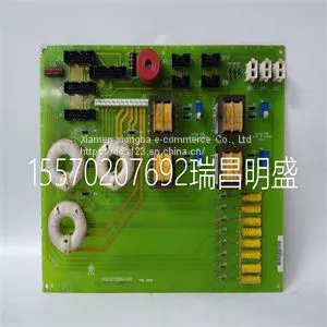
Module Spare Parts DS200TCEBG1ACE

Related Products
-
 Module Spare Parts DS200TCQCG1BGFUS$ 1 - 100000MOQ: 1 Piece
 -
Module Spare Parts DS200TCTGG1AFFUS$ 1 - 100000MOQ: 1 Piece
-
Module Spare Parts DS215KLDBG1AZZ03A DS200KLDBG1ABCUS$ 1 - 100000MOQ: 1 Piece
-
Module Spare Parts DSAI130 57120001-P5US$ 1 - 100000MOQ: 1 Piece
-
Module Spare Parts DSDP150 57160001-GFUS$ 1 - 100000MOQ: 1 Piece
Focus on DCS, PLC, robot control system and large servo system.
Main products: various modules / cards, controllers, touch screens, servo drivers.
Advantages: supply of imported original products, professional production parts,
Fast delivery, accurate delivery time,
The main brands include ABB Bailey, Ge / fuanc, Foxboro, Invensys Triconex, Bently, A-B Rockwell, Emerson, ovation, Motorola, xyvom, Honeywell, Rexroth, KUKA, Ni, Deif, Yokogawa, Woodward, Ryan, Schneider, Yaskawa, Moog, prosoft and other brands
| DS200TCEBG1ACE |
When you install and connect all the high‐speed stacking cables to the switches in the stack, the following occurs once power is applied to the switches: • The switch that will manage (manager) the stack is automatically established with all other switches established as member switches in the stack. When the switches complete their initialization, one of the switches in the stack will illuminate its MGR LED, indicating that it is the stack manager. The MGR LED on each member switch will be off. • The hierarchy of the switches that will function as backup manager is also determined in case the current manager malfunctions, is powered down, or is disconnected from the stack. • The Console port on each member switch is deactivated. Only the Console port on the manager switch is active for out‐of band configuration to set the IP address, password, and other configuration settings. Once you know which switch is the manager, proceed to “Connecting to the Console Port for Local Management” on page 2‐18. Recommended Procedures for New and Existing Stacks Installing a New Stackable System of Up to Eight Switches Use the following procedure to install a new stack of up to eight switches out of the box. Before applying power, make all physical connections with the stack cables as described in “Connecting Stacking Cables” on page 2‐5. 1. Once all of the stack cables have been connected, individually power on each switch from top to bottom (connecting power to a switch is described in “Connecting AC Power” on page 2‐9). If the switches are powered on almost simultaneously, the system will automatically select the first one that powers up as the Master switch and the others as member switches. The switches are assigned unit IDs in the order that they become fully operational. You can control the unit ID assignment according to the physical position in a stack. When you power up each switch and allow it to become fully operational before applying power to the next switch, the first one becomes the manager and all the next switches will join that stack (regardless of priority, firmware revision, or MAC address). The switches are assigned unit IDs in the order that you power on each switch. 2. Connect to the Console port of the manager switch. 3. (Optional) If desired, change the management switch using the set switch movemanagement command as described in the Enterasys A4 CLI Reference Guide. 4. Once the desired master switch has been selected, reset the system using the reset command as described in the Enterasys A4 CLI Reference Guide

Send Inquiry to This Supplier


You May Also Like
-
Module Spare Parts DSDX452 5716075-PUS$ 1 - 100000MOQ: 1 Piece
-
Module Spare Parts DSMB-01C 64691929US$ 1 - 100000MOQ: 1 Piece
-
Module Spare Parts IC693ACC323BUS$ 1 - 100000MOQ: 1 Piece
-
Module Spare Parts IC693DNM200US$ 1 - 100000MOQ: 1 Piece
-
Module Spare Parts IC695CRU320US$ 1 - 100000MOQ: 1 Piece
-
Module Spare Parts IC698CHS009US$ 1 - 100000MOQ: 1 Piece
-
Module Spare Parts IC698CPE030US$ 1 - 100000MOQ: 1 Piece
-
Module Spare Parts IC698CPE040US$ 1 - 100000MOQ: 1 Piece
-
Module Spare PartsIC698CRE040US$ 1 - 100000MOQ: 1 Piece
-
Module Spare Parts IC698CRE040-HNUS$ 1 - 100000MOQ: 1 Piece


