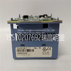
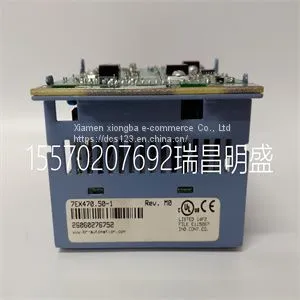
Module Spare Parts 7EX470.50-1

Module Spare Parts 7EX470.50-1 photo-1
US$ 1 - 100000 MOQ: 1 Piece
Key Specifications
Get Latest Price
Brand Name:
Miscellaneous brand
Model Number:
7EX470.50-1

Payment & Shipping
Payment Methods:
Port of Shipment:
xiamen
Delivery Detail:
1 days
Brand Name Miscellaneous brand
Model Number 7EX470.50-1


Focus on DCS, PLC, robot control system and large servo system.

Main products: various modules / cards, controllers, touch screens, servo drivers.

Advantages: supply of imported original products, professional production parts,

Fast delivery, accurate delivery time,

The main brands include ABB Bailey, Ge / fuanc, Foxboro, Invensys Triconex, Bently, A-B Rockwell, Emerson, ovation, Motorola, xyvom, Honeywell, Rexroth, KUKA, Ni, Deif, Yokogawa, Woodward, Ryan, Schneider, Yaskawa, Moog, prosoft and other brands


7EX470.50-1
Determines the behavior of the module in the event of a CPU STOP. Potential group A potential group consists of a group of directly adjacent I/O modules within an ET 200SP station, which are supplied via a common supply voltage. A potential group begins with a light-colored BaseUnit through which the required voltage is supplied for all modules of the potential group. The light-colored BaseUnit interrupts the three self-assembling voltage buses P1, P2 and AUX to the left neighbor. All additional I/O modules of this potential group are plugged into dark-colored BaseUnits. You take the potential of the self-assembling voltage buses P1, P2 and AUX from the left neighbor. A potential group ends with the dark-colored BaseUnit, which follows a light-colored BaseUnit or server module in the station configuration. Parameters/address space 4.3 Address space Digital output module DQ 16x24VDC/0.5A ST (6ES7132-6BH01-0BA0) Manual, 02/2019, A5E03574420-AF 17 4.3 Address space The module can be configured differently in STEP 7; see following table. Depending on the configuration, additional/different addresses are assigned in the process image output/input. Configuration options of DQ 16x24VDC/0.5A ST You can configure the module with STEP 7 (TIA Portal) or with a GSD file. If you configure the module by means of a GSD file, the configurations are available under various short designations/module names; see the table below. The following configurations are possible: Table 4- 2 Configuration options with GSD file Configuration Short designation/module name in the GSD file Configuration software, e.g. with STEP 7 (TIA Portal) Integrated in hardware catalog STEP 7 GSD file PROFINET IO GSD file PROFIBUS DP 1 x 16-channel without value status DQ 16x24VDC/0.5A ST V0.0 V14, SP1 or higher with HSP 0222 X X 1 x 16-channel with value status DQ 16x24VDC/0.5A ST V0.0, QI V14, SP1 or higher with HSP 0222 X --- Evaluating the value status An additional two bytes are allocated in the input address space if you enable the value status for the digital module. Bits 0 to 15 in these bytes are assigned to a channel. They provide information about the validity of the digital value. Bit = 1: No fault is present on the channel. Bit = 0: Channel is deactivated or there is a fault on the module. If a fault occurs on a channel with this module, the value status for all channels is 0. Parameters/address space 4.3 Address space Digital output module DQ 16x24VDC/0.5A ST (6ES7132-6BH01-0BA0) 18 Manual, 02/2019, A5E03574420-AF Address space The following figure shows the assignment of the address space for the DQ 16x24VDC/0.5A ST with value status (Quality Information (QI)). The addresses for the value status are only available if the value status is enabled. Figure 4-1 Address space of DQ 16×24VDC/0.5A ST with value status Digital output module DQ 16x24VDC/0.5A ST (6ES7132-6BH01-0BA0) Manual, 02/2019, A5E03574420-AF 19 Interrupts/diagnostic alarms 5 5.1 Status and error display LED display DQ 16x24VDC/0.5A ST. ① DIAG (green/red) ② Channel status (green) ③ PWR (green) Figure 5-1 LED display Interrupts/diagnostic alarms 5.1 Status and error display Digital output module DQ 16x24VDC/0.5A ST (6ES7132-6BH01-0BA0) 20 Manual, 02/2019, A5E03574420-AF Meaning of the LEDs The following tables contain the meaning of the status and error displays. Remedial measures for diagnostic alarms can be found in chapter Diagnostic messages (Page 22). DIAG LED Table 5- 1 DIAG LED fault display DIAG LED Meaning Off Backplane bus supply of the ET 200SP not OK Flashing Module not configured On Module parameters assigned Flashing Module diagnostics is available LED channel status Table 5- 2 LED channel status display LED channel status Meaning Off Channel deactivated or activated and process signal = 0 On Channel activated and process signal = 1 PWR LED Table 5- 3 Status display of the PWR LED PWR LED Meaning Off Supply voltage L+ missing On Supply voltage L+ present Interrupts/diagnostic alarms 5.2 Interrupts Digital output module DQ 16x24VDC/0.5A ST (6ES7132-6BH01-0BA0) Manual, 02/2019, A5E03574420-AF 21 5.2 Interrupts The digital output module DQ 16×24VDC/0.5A ST supports diagnostic interrupts. Diagnostics interrupts The module generates a diagnostic interrupt at the following events: ● Short-circuit ● Wire break ● Parameter assignment error ● Supply voltage missing
Product Tags: spot goods , Large warehouse management

Send Inquiry to This Supplier

* Message
0/5000

Want the best price? Post an RFQ now!
Verified Business License
Main Markets
North America, South America, Eastern Europe, Southeast Asia, Africa, Oceania, Mid East, Eastern Asia, Western Europe, Central America, Northern Europe, Southern Europe, South Asia, Domestic Market

Recommended Categories

Explore top categories and find suppliers for your specific needs