

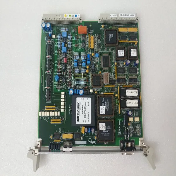
TEAM BL0170

Related Products
Brand:TEAM
Type:BL0170
Origin: the United States
Warranty: 365 days
Colour: new/used
Shipping method: Courier delivery
Module of PLC, DCS, ESD system card, the card is a vibration monitoring system, steam turbine control system module, the advantages of the gas generator spare parts brand: Allen Bradley, BentlyNevada, ABB, Emerson Ovation, Honeywell DCS, Rockwell ICS Triplex, FOXBORO, Schneider PLC, GE Fanuc, Motorola, HIMA, TRICONEX, Prosoft etc. Various kinds of imported industrial parts of our products are widely used in metallurgy, petroleum, glass, aluminum manufacturing, petrochemical industry, coal mine, papermaking, printing, textile printing and dyeing, mechanical, electronic manufacturing, automobile manufacturing, plastic machinery, electric power, water conservancy, water treatment/environmental protection, boiler heating, energy, power transmission and distribution and so on.
Status LED Blink Code Fault Description Possible Cause 17 SFD Communication Error Feedback cable not connected at the drive or at the motor. Feedback cable shield not connected. Defective feedback cable Internal SFD failure. Excessive electrical noise in the drive environment causing communications interference. 18 Option Card Watch Dog Time out Communication error between option card and main board. 19 Position Error Too Large Check ExtFaults: ExtFaults = Step size over flow means GearOut/GearIn is too large. ExtFaults = Position error over flow means that the following error, = PosErr, has exceeded ±128 revs. Check if the motor is stalling or if the commanded speed is higher than the motor can achieve at the present bus voltage. 20 Option Card Fault Check ExtFaults: If ExtFaults is AuxFBFault, then the AuxFB device is in error. Check the AuxFB faults: AuxFBEnDatFlt, AuxFBPTCFlt or AuxFBSCDFlt. Check to make sure that the drive is set up for the correct feedback device and that the device is functioning correctly. If ExtFaults is “No Extended Fault,” then this was a fault induced by the controller, such as SynqLost.

Fault Generation The following sequence occurs when the protection circuits generate a fault. • One or more faults are detected by the control logic. • The fault source is latched – only for latched faults. • The output stage is disabled. • The LED indicates the appropriate fault code. • For non-latched faults. When the fault condition is cleared, the drive re-enables automatically. Latched faults are cleared by setting the Enable/ input to the disable state or by cycling (off/on) the Control Power. NOTE: The large bus capacitors store substantial energy. To use the control power to reset a fault, the power should be removed for at least 30 seconds to ensure that the fault resets. Self-resetting faults disable the drive and do not return it to normal operation until 50-100 ms after the fault condition clears. When multiple faults occur, the highest priority fault is reported. After the fault is cleared and the drive is reset by cycling the enable input, the next highest priority fault that still exists will be displayed.

Send Inquiry to This Supplier

You May Also Like
-
MITSUBISHI A1S68DAVUS$ 1085 - 2076MOQ: 1 Piece
-
MITSUBISHI A1SJ51T64US$ 1085 - 2076MOQ: 1 Piece
-
SUGAHARA S-0000 REV.CUS$ 1108 - 2018MOQ: 1 Piece
-
K3NX-AD1A-FLK4US$ 1111 - 2021MOQ: 1 Piece
-
ORIENTAL MOTOR 2GK180KUS$ 1112 - 2022MOQ: 1 Piece
-
PACIFIC SCIENTIFIC 33VM52-000-4US$ 1112 - 2022MOQ: 1 Piece
-
ABSOLUTE API4380-GUS$ 1113 - 2023MOQ: 1 Piece
-
ALSTOM V4561983-0100 V4559856US$ 1113 - 2023MOQ: 1 Piece
-
ELMA 1900002919-0000RUS$ 1115 - 2025MOQ: 1 Piece
-
Eaton MPB2-TPUS$ 1120 - 2030MOQ: 1 Piece


