








 Contact Platform Support
 Help Center
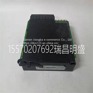
Module Spare Parts UR6AH



Related Products
-
 Module Spare Parts VT-HNC100-1-23W-08-P-0 R900958999US$ 1 - 100000MOQ: 1 Piece
 -
Module Spare Parts07AC91 GJR5252300R0101US$ 1 - 100000MOQ: 1 Piece
-
Module Spare Parts 07DC91C GJR5251400R0202US$ 1 - 100000MOQ: 1 Piece
-
Module Spare Parts 07EA90-SI GJR5251200R0101US$ 1 - 100000MOQ: 1 Piece
-
Module Spare Parts 07KR51 1SBP260011R1001US$ 1 - 100000MOQ: 1 Piece
Focus on DCS, PLC, robot control system and large servo system.
Main products: various modules / cards, controllers, touch screens, servo drivers.
Advantages: supply of imported original products, professional production parts,
Fast delivery, accurate delivery time,
The main brands include ABB Bailey, Ge / fuanc, Foxboro, Invensys Triconex, Bently, A-B Rockwell, Emerson, ovation, Motorola, xyvom, Honeywell, Rexroth, KUKA, Ni, Deif, Yokogawa, Woodward, Ryan, Schneider, Yaskawa, Moog, prosoft and other brands
| UR6AH |
Typical Applications (continued) The switching losses are very difficult to calculate due to changing parasitics of a given MOSFET in operation. Often, the individual MOSFET datasheet does not give enough information to yield a useful result. Equation 38 and Equation 39 give a rough idea how the switching losses are calculated: (38) (39) 8.2.1.2.7 Input Capacitor Selection Due to the presence of an inductor at the input of a boost converter, the input current waveform is continuous and triangular, as shown in Figure 32. The inductor ensures that the input capacitor sees fairly low ripple currents. However, as the input capacitor gets smaller, the input ripple goes up. The rms current in the input capacitor is given by: (40) The input capacitor should be capable of handling the rms current. Although the input capacitor is not as critical in a boost application, low values can cause impedance interactions. Therefore a good quality capacitor should be chosen in the range of 100 µF to 200 µF. If a value lower than 100 µF is used, then problems with impedance interactions or switching noise can affect the LM3481. To improve performance, especially with VIN below 8 V, it is recommended to use a 20Ω resistor at the input to provide a RC filter. This resistor is placed in series with the VIN pin with only a bypass capacitor attached to the VIN pin directly (see Figure 34). A 0.1-µF or 1-µF ceramic capacitor is necessary in this configuration. The bulk input capacitor and inductor will connect on the other side of the resistor with the input power supply. Figure 34. Reducing IC Input Noise 8.2.1.2.8 Output Capacitor Selection The output capacitor in a boost converter provides all the output current when the inductor is charging. As a result it sees very large ripple currents. The output capacitor should be capable of handling the maximum rms current. The rms current in the output capacitor is

Send Inquiry to This Supplier


You May Also Like
-
Module Spare Parts 07KT98 GJR5253100R3160US$ 1 - 100000MOQ: 1 Piece
-
Module Spare Parts 086318-002 086318-501US$ 1 - 100000MOQ: 1 Piece
-
Module Spare Parts 086339-001 004707001474US$ 1 - 100000MOQ: 1 Piece
-
Module Spare Parts 0880001-01US$ 1 - 100000MOQ: 1 Piece
-
Module Spare Parts104X905BA603 G-95-149-H-9550US$ 1 - 100000MOQ: 1 Piece
-
Module Spare Parts106M1081-01US$ 1 - 100000MOQ: 1 Piece
-
Module Spare Parts 10QT01 GJR2209300R0001 10QT01A-ER0001US$ 1 - 100000MOQ: 1 Piece
-
Module Spare Parts 216EA62 1MRB178066R1E 1MRB150083R1E 1MRB300162R0008US$ 1 - 100000MOQ: 1 Piece
-
Module Spare Parts 216NG63A HESG441635R1 HESG216877KUS$ 1 - 100000MOQ: 1 Piece
-
Module Spare Parts 216VC62AUS$ 1 - 100000MOQ: 1 Piece


