

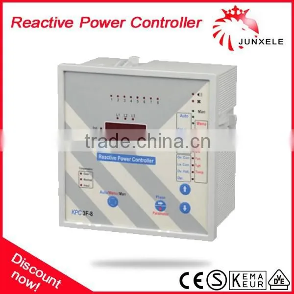
KPC 3F Intelligent Reactive Power Compensation Controller

Related Products
-
 KMM 01U Amper Voltage Frequency True RMS Digital MultimeterUS$ 1 - 100MOQ: 100 Pieces
 -
KMV 01U Voltage Frequency True RMS Digital MultimeterUS$ 1 - 100MOQ: 100 Pieces
-
KDA Electronic Digital Panel AmpermeterUS$ 1 - 100MOQ: 100 Pieces
-
KDV Electronic Digital Three Phase VoltmeterUS$ 1 - 100MOQ: 100 Pieces
-
KFM Electronic Digital Frequency MeterUS$ 1 - 100MOQ: 100 Pieces
Intelligent Reactive power compensation controller
General Specifications
KPC 3F, compensates the system according to three phases' reactive power by measuring voltage and current from three |
Buttons and Lights
1 - 1,2,3.....12: Shows the steps which capacitor is switched on. |
Using The Controller
1 - Selecting operation mode: "Auto/Menu/Man" button is used for selecting mode. If "Auto" lights, the controller is in |
Warnings and Explanations
1 - Over Current Alarm: If measured seconder current value of current transformer is bigger than adjusted over current value, "Over Cur." lights. If over current alarm is active and this continues 60sec.,the alarm is turned on. |
General Rules for Compensation
1 - Current transformer that is connected reactive power controller must have .../5A ratio. |
General Rules for Compensation
C/k adjustment, determines least power that is wanted to control. It equals first step’s capacitor power, divide by current |
Technical Specifications
Connection Scheme
Dimensions
Installation of A Compensation System
|
Example: There is a system that has Cosφ=0,80 and 50kVA total pwer. What are the total capacitor power that is needed and
Other products
|
1.We are Alibaba Assessed Gold Supplier. relay
2.We are a factory manufacturing circuit breaker,contactor,transformer,best production capability ,best quality control, Best Service .
3.100% QC inspection Before Shippment. relay
4. CE/SAA/SEMKO/KEMA/VDE listed,competitve price.
How to contact us?
Please send your Inquiry Details in the Below , Click "Send" Now! relay

Send Inquiry to This Supplier

You May Also Like
-
Integrated Electrical Control Cabinet Electric Energy Conversion Circuit Isolation Industrial Control Equipment CabinetNegotiableMOQ: 1 Set
-
Control Panel for Cable Conveyor, Pusher, Puller, Feeder, Hauler, Cable Dog – Start/Stop, Forward/Reverse, Speed Control & Frequency Setting UnitUS$ 50 - 80MOQ: 1 Combo
-
Dry Type Transformer Three Phase 480v to 208y/120v 315kva 1000kva No Reviews YetUS$ 12999 - 15000MOQ: 1 Piece
-
GXGN-12 Smart Solid Insulating CabineNegotiableMOQ: 1 Piece
-
IP67 Plastic Portable Waterproof Electrical Power Distribution Boards BoxUS$ 10MOQ: 100 Pieces
-
Power Distribution Cabinet & BoxNegotiableMOQ: 2000 Sets
-
GPRS Outdoor Alarm Controller S250,Three-Phase Power Line Protection,NC/NO/EOL Dry Contact,Remote Relay OutputUS$ 1 - 10MOQ: 1 Set
-
Chinese Outdoor Electric Meter Box Manufacturer With 30 Years ExperienceUS$ 2 - 15MOQ: 500 Pieces
-
Small Gear Reducer MotorUS$ 8 - 10MOQ: 1 Piece
-
Explosion Proof Electrical EquipmentUS$ 500 - 5,000MOQ: 1 Set


