

RF Microwave Time Delay System


Related Products
-
 SOI High-speed VOAUS$ 1950MOQ: 1 Piece
 -
SOI Nanosecond High Speed Switch 2x2US$ 1800MOQ: 1 Piece
-
AWG Arrayed Waveguide Grating 50~200GNegotiableMOQ: 1 Unit
-
Motorized Delay Line Fiber Optic Device for OCT EquipmentUS$ 370 - 1200MOQ: 1 Unit
-
Narrow-linewidth Fiber Laser for Fiber SensingNegotiableMOQ: 1 Unit
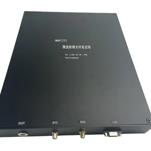
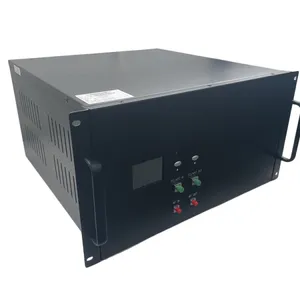
RF Microwave Delay System
Definition
RF microwave delay system is a device that uses optical principles to delay microwave signals. It converts the input radio frequency (RF) signal into an optical signal, transmits it a certain distance in an optical fiber or other optical medium, and then converts it back into an RF signal, thus achieving a time delay of the signal. This process not only maintains the integrity of the signal spectrum but also precisely controls the delay time through the physical length of the optical fiber.
Working Principle
The working principle of an RF microwave delay system mainly includes three steps: electro-optic conversion, optical signal propagation, and photoelectric conversion.
1. Electro-optic Conversion: The input microwave electrical signal is first sent to an electro-optic converter (such as a laser diode LD), which modulates the electrical signal into an optical signal. This step realizes the conversion from microwave signal to optical signal.
2. Optical Signal Propagation: The modulated optical signal is transmitted through an optical fiber or other optical medium. Optical fiber, as a medium, is very suitable for long-distance and high-quality signal transmission due to its low loss, wide bandwidth, and anti-interference characteristics. The propagation time of the optical signal in the optical fiber depends on the length of the fiber, thus achieving the delay of the microwave signal.
3. Photoelectric conversion: After the optical signal propagates a certain distance in the optical fiber, it is converted back into a microwave electrical signal by a photodetector (PD). The converted electrical signal retains the spectral characteristics of the original signal, but is delayed relative to the original signal.
Advantages:
High bandwidth
Electromagnetic interference resistance
Selectable wavelengths: 1310nm/1490nm/1550nm
Surge protection, reliable power supply, environment adaptability
Adaptive temperature compensation capability for stable light
source output control
Compact size
Suitable for military standards
Applications: Radar inspection
Parameter |
Unit |
Specifications |
Frequency Range |
GHz |
0.2 – 2.5 or 1~18GHz |
Delay Time Range |
— |
Customizable, range up to 10nS ~ 300uS |
Delay Step Resolution |
time |
11/9/7bit programmable optional |
Delay Accuracy |
Ns |
1ns |
Channel Switching Time |
— |
Optional |
Max Input RF Signal |
dBm |
10 |
In-band Gain Flatness |
dB |
±1.5 |
Power Consistency at Different In-band Delay Values |
dB |
±1 |
In-band Power Stability |
dB |
≤1@3h, typical 0.7@3h |
In-band Reverse Isolation |
dB |
-58 |
Base Delay |
Ns |
25 |
Single RF Insertion Loss |
dB |
Min -55 ~ max -70@ |
Group Delay Ripple |
ps |
|
Noise Floor |
dBm |
|
Input/Output Impedance |
Ohm |
50 |
Phase Noise |
dBc |
|
Power Supply |
VDC |
5~12V |
Power Consumption |
W |
|
Laser Output Wavelength |
nm |
1310/1550 |
The above does not include the RF processing indicators. If the requirements exceed this standard, external RF processing will be necessary.

Send Inquiry to This Supplier

You May Also Like
-
16x16 MEMS Optical Switch MatrixNegotiableMOQ: 1 Unit
-
Multi-channel Channels Variable Optical Attenuator ModuleNegotiableMOQ: 1 Unit
-
Fiber Amplifier EDFA for Optical CommunicationNegotiableMOQ: 1 Unit
-
MEMS Optical SwitchNegotiableMOQ: 1 Unit
-
MEMS VOA(variable Optical Attenuator) ComponentsNegotiableMOQ: 1 Unit
-
Broadband RF Directly Modulated DFB LaserNegotiableMOQ: 1 Unit
-
C+L Band ASE Broadband Source for Fiber SensingNegotiableMOQ: 1 Unit
-
Speial Laser for GAS Detection Butterfly-shaped DFB LaserNegotiableMOQ: 1 Unit
-
DAS High-speed RF Data Acquisition Boards for Wirless CommunicationNegotiableMOQ: 1 Unit
-
10W Erbium-doped Fiber Amplifier for LiDARNegotiableMOQ: 1 Unit


