

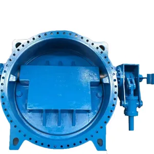
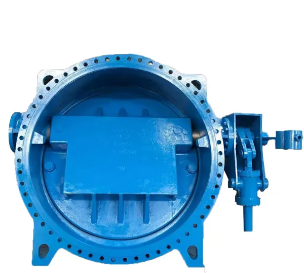
Hydraulic Control Butterfly Valve
Related Products
-
 Synthetic Rubber Flange Center Line Plate Butterfly Valve in Water PlantNegotiableMOQ: 1 Set
 -
Stainless Steel Double Eccentric Butterfly Valve With PTFE Seat for Chemical IndustryNegotiableMOQ: 1 Set
-
General Purpose Flanged Centric Type Butterfly Valve in Water PlantNegotiableMOQ: 1 Set
-
Low Price Wholesale Custom Flanged Centric Type Butterfly ValveNegotiableMOQ: 1 Set
-
PN16 Flanged Hydraulic Butterfly Valve With PTFE Seat for Chemical IndustryNegotiableMOQ: 1 Set
Characteristics of Hydraulic
Control Butterfly Valve
Energy storage device more secure
Relying on its own weight storage or by two accumulators storage, can be automatically shut of the valve without extermal energy
Multi use more flexible
Reliable sealing. small fow resistance coefficient
The seal is more efficient
A high degree of automation, local, remote and linkage control
Control mode of higher
PLC intelligent control system, can realize the text, touch screen and other humanized operation
interface, can also adopt ordinary relay system .
More intelligent interface
The hydraulic system of small power motor, high work eficiency, good pressure maintaining performance, oil pump start-up timinterval length .
The higher working efficiency
There are obvious opening indication and mechanical spacing adjusting mechanism, a travel switch device waterproof dustprooidesign, not exserted. stable performance . long service life
A londer life
According to a predetermined program and other pipeline equipment linkage operation
Automatic operation more perfect
Closed to achieve slow closing function, effectively eliminate water hammer, water pump and pipe network security protection
The protection function is more secure
Can replace the water pump outet valve and check valve, and the machine, electricity, liquid in a body, has the advantages of smaloccupation area
Working Principle of Hydraulic
Control Butterfly Valve
Opening
Upon opening hydraulic control butterfly valve, under the acting force of hydraulic control station and lit cylinder, disc wil rotate by90'driven by it arm, weight dropper rod and valve shaft etc . Meanwhile, the acting force of hydraulic control station and lift cylinderwil verically lift the weight dropper through lift arm and weight dropper rod, making the gravity of weight dropper into potential energto be used for valve closing.
Lock
Composed of drive cylinder, mechanical lock shaft, electromagnetic lock shaft and electromagnet etc, the locking mechanism ofhydraulic control buterly valve is provided with the dual function of mechanical and electromagnetic lockup . When valve is fulyopened, the acling force of drive cylinder drives the mechanical lock shaft into the locking position for primary lockout . and then theforce of electromagnet drives the electromagnetic lock shaft for fnal lockout . The process of lockout is completely automatic withoutany letup under the help of a series of position switches The huge acting force of weight dropper is completely endured by mechanicalock shaft . The withdrawal of mechanical lock shaft is restricted by electromagnetic lock shaf, while the withdrawal of electro-magneticock shaft is controled by the force of electromagnet . Provided that electromagnet is elect rife d , both electromagnetic lock shaft andmechanical lock shaft are under well control . No matter how long the valve is kept open and how weight the weight dropper is, theweight dropper(disc) wil not fall a tiny bit, thus to ensure disc always fully opened(state of minimum fuid resistance) . lt doesn't needextra oiling and pressure in the process .
Closing
Valve is closed by A: man-made closed; B: closed due to failure or power breakdown of pump or valve; C: closed due to breakdownof outside wire . No matter in which case, as soon as the electromagnet is disconnected to power, valve will be closed according to thepredetermined procedure . Upon the breakdown of electromagnet, electromagnetic force will disappear immediately. Electromagneticock shaft wil be unlocked when electromaanetic force disappears . and the mechanical lock shaft will also be unlocked upon the lossof restriction of electromagnetic lock shaf Here the potential energy of weight dropper wll immediately close the disc driven by weightdropper rod, ift arm and valve shaft etc, by the procedures of quick closing, cushioning and slow closing. The whole process is donewithout any letup . in the process of closing of hydraulic control buterfy valve, the oil liquor in the lower cavity of lift cvlinder shal bedischarged. For reasons given above, the method to control and adiust the speed of oil discharging in lfing cylinder can efectivelycontrol the closing speed of valve . The closing process of hydraulic control valve goes through the three procedures of quick closing.cushioning and slow closing. Both the time and angle of quick and slow closing are adjustable .

Send Inquiry to This Supplier


You May Also Like
-
Double Eccentric Butterfly Valve With On-Site Technical SupportNegotiableMOQ: 1 Set
-
Flanged Concentric Disc Butterfly Valve With PTFE Lining for Chemical Processing ApplicationsNegotiableMOQ: 1 Set
-
Wafer Type Soft Sealed Butterfly Valve for Water Supply and Industrial Pipeline SystemNegotiableMOQ: 1 Piece
-
Wafer Type Butterfly Valve With Stainless Steel Disc for Water, Oil and Gas PipelinesNegotiableMOQ: 1 Piece
-
Double Flanged Eccentric Butterfly Valve for Water Supply and Industrial PipelineNegotiableMOQ: 1 Piece
-
Double Flanged Eccentric Butterfly ValveNegotiableMOQ: 1 Piece
-
High Performance Stainless Steel Wafer Butterfly Valve, Full Bore Design for Industrial PipesNegotiableMOQ: 1 Piece
-
Stainless Steel Wafer Butterfly Valve With Multiple Disc Options (Concentric, Double/ Triple Eccentric)NegotiableMOQ: 1 Piece
-
Compact Wafer Type Butterfly Valve With EPDM Seat, Suitable for Water and Neutral MediaNegotiableMOQ: 1 Piece
-
Double Eccentric Butterfly Valve DN50-1200 High Performance for Water Treatment PlantsNegotiableMOQ: 1 Set


