








 Contact Platform Support
 Help Center
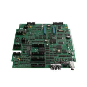
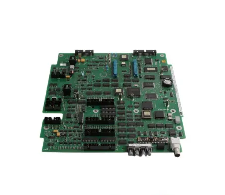
ABB UNS2880B-P V1 3BHE014967R0001 Control Board



Related Products
-
 ABB UFC718AE01 HIEE300936R0101 Main Circuit Interface BoardNegotiableMOQ: 1 Piece
 -
ABB RF522 3BSE000743R1 Including BackplaneNegotiableMOQ: 1 Piece
-
ABB UFC760BE41 3BHE004573R0141 Interface BoardNegotiableMOQ: 1 Piece
-
ABB PFTL201C-50KN 3BSE007913R50 Pressure SensorNegotiableMOQ: 1 Piece
-
ABB 5SHY3545L0016 3BHB020720R0002 Integrated Gate-Commutated Thyristor (IGCT)NegotiableMOQ: 1 Piece
I. Overview
ABB UNS2880B-P V1 3BHE014967R0001 is an industrial I/O module specifically designed for automation scenarios requiring high-reliability signal processing and interconnection between field devices and control systems. Its core positioning is to act as a signal hub between field terminal devices and central control systems, undertaking the key responsibilities of signal acquisition, conversion, transmission and command interaction. It realizes seamless connection between field devices such as sensors and actuators and central control systems such as PLC, DCS and SCADA, providing core data link support for the stable operation of industrial automation processes.
With its highly integrated I/O channel design, industrial-grade rugged performance and flexible compatibility, this product is widely used in various industrial fields such as manufacturing, oil and gas, power, and chemical engineering. It can be adapted to multiple scenarios including manufacturing automation data acquisition, process control monitoring, and energy management system interconnection, and can fully meet the supporting needs of new industrial project construction, existing system upgrading and transformation, as well as equipment maintenance and replacement.
II. Product Features
Highly Integrated I/O Channel Design: Adopting a highly integrated I/O channel layout, it can be configured as digital or analog I/O type according to actual application requirements. It can access multiple channels of field signals simultaneously, greatly improving the data processing capability of a single module, reducing the number of modules required by the system, saving installation space in the control cabinet, and lowering system integration costs.
Industrial-Grade Rugged and Reliable Performance: Designed in accordance with industrial-grade environmental application standards, it has excellent anti-interference capability and environmental adaptability, and can operate stably in complex industrial environments with dust and vibration. The core circuit adopts a redundant design concept, effectively reducing the risk of single-point failures and ensuring the continuity and reliability of signal processing and transmission.
Wide System and Protocol Compatibility: It is fully compatible with ABB's full range of control systems, and supports various mainstream industrial communication protocols such as Modbus, Profibus and EtherNet/IP. It can be seamlessly integrated into various existing automation system architectures without major adjustments to the system layout, significantly improving the flexibility of system expansion and upgrading.
Flexible Configurability: It supports flexible configuration of I/O channel types, signal ranges, communication parameters, etc. through upper computer software or local configuration interfaces. It can accurately adapt to the signal characteristics of different field devices (such as voltage-type and current-type signals), and can quickly respond to the personalized application needs of different industries and scenarios.
Intelligent Signal Processing Capability: Equipped with a built-in high-performance signal processing unit, it can complete accurate conversion between analog and digital signals, and has functions such as signal filtering, amplification and calibration. It effectively improves the accuracy of signal transmission, reduces the impact of field environmental interference on signal quality, and provides high-quality data support for the precise decision-making of control systems.
III. Technical Parameters
1. Core Basic Parameters
Product Model: UNS2880B-P V1
Order Number: 3BHE014967R0001
Product Type: Industrial I/O Module (configurable as digital/analog I/O)
Manufacturer: ABB (ASEA Brown Boveri)
Core Functions: Field signal acquisition, signal conversion (analog/digital), data transmission, control command interaction
Compatible Systems: PLC, DCS, SCADA and other industrial control systems
Mounting Method: DIN rail mounting/panel mounting (modular design, compatible with standard industrial control cabinets)
Application Scenarios: Manufacturing automation data acquisition, oil and gas process control, power industry monitoring, chemical process control, energy management systems (interconnected with devices such as electric energy meters and flowmeters)
2. Electrical Performance Parameters
Supply Voltage: Standard 24V DC (external power supply, compatible with AC power supply in some scenarios, subject to specific configuration confirmation)
I/O Signal Type: Configurable digital input/output, analog input/output
Voltage Signal Range: Supports 24V DC digital signals, 0-10V analog signals (adapted according to configuration)
Current Signal Range: Supports standard industrial current input/output (e.g., 4-20mA, subject to actual configuration)
Processing Speed: 1500μs (high-speed signal processing, meeting real-time control requirements)
I/O Points: Typical configuration is a 16-channel isolated input module, supporting a maximum of 500 input/output points each (expandable)
Communication Protocols: Supports Modbus RTU, Profibus, EtherNet/IP, and some versions are compatible with HART-IP protocol
Communication Interfaces: RS485/RS232 serial port, Ethernet interface (supporting multi-device networking and remote monitoring)
3. Environmental and Physical Parameters
Protection Class: IP20 (basic industrial protection, dust-proof and protection against solid foreign object intrusion, suitable for indoor industrial environments)
Operating Temperature: -20℃ ~ 60℃ (wide-temperature design, adapted to most industrial field temperature environments)
Storage Temperature: -40℃ ~ 85℃
Relative Humidity: 5% ~ 95% RH (non-condensing)
Electromagnetic Compatibility: Complies with industrial-grade electromagnetic compatibility standards, with strong anti-electromagnetic interference capability
Dimensions: Approximately 290mm (length) × 450mm (width) × 47mm (height) (modular and lightweight design)
Weight: Approximately 0.67kg
IV. Working Principle
The core working principle of ABB UNS2880B-P V1 3BHE014967R0001 is a closed-loop data link process of "signal acquisition - processing and conversion - data transmission - command execution - status feedback". Through the collaborative work of its internal signal processing unit, communication unit and I/O interface unit, it realizes two-way interaction between field devices and central control systems. The specific working process can be divided into five core stages:
Stage 1: Initialization and Parameter ConfigurationAfter the module is connected to a 24V DC external power supply, it completes initialization and startup. Operation and maintenance personnel configure the I/O channel types (digital/analog), signal ranges, communication protocols and parameters (such as baud rate and IP address) through upper computer software or local configuration interfaces. At the same time, the module automatically completes internal circuit self-test and channel calibration to ensure that all functional modules are in a ready state.
Stage 2: Field Signal AcquisitionThrough the configured I/O channels, the module continuously collects signal data from field devices—the digital channels collect switch status signals (such as on/off, start/stop) from devices like sensors and limit switches, while the analog channels collect continuous quantity signals (such as voltage/current signals corresponding to pressure, flow and temperature) from devices like transmitters and flowmeters. During the acquisition process, the built-in filter circuit performs preliminary noise reduction on the signals.
Stage 3: Signal Processing and ConversionThe signal processing unit performs in-depth processing on the collected raw signals—analog signals are converted into digital signals recognizable by the control system through the A/D conversion module, and digital signals undergo level calibration and validity verification. At the same time, signal range conversion is completed to convert field signals into a standard format compatible with the control system, ensuring data accuracy and consistency.
Stage 4: Data Transmission and Command ReceptionThe processed field data is uploaded to the central control system (PLC/DCS/SCADA) through the communication unit (based on protocols such as Modbus and Profibus), providing real-time data support for system scheduling and decision-making. Meanwhile, the communication unit continuously receives control commands (such as actuator start/stop and parameter adjustment) issued by the control system and transmits them to the command parsing unit.
Stage 5: Command Execution and Status FeedbackThe command parsing unit decodes the received control commands and sends them to field devices such as actuators through the corresponding I/O channels to drive the devices to complete corresponding actions. At the same time, the module real-time monitors the command execution status and its own operating status (such as power supply stability and channel faults), feeds back the status information to the control system, and triggers an alarm prompt if an abnormality is detected, providing accurate guidance for operation and maintenance personnel to troubleshoot and handle problems.
V. Common Fault Troubleshooting
1. Communication Link Interruption / Abnormal Data Transmission
Phenomenon: The module cannot establish communication with the central control system (PLC/DCS); the control system cannot receive the field data uploaded by the module or execute the control commands issued; data transmission is frequently interrupted, with packet loss or data distortion.
Causes: Loose, poor contact or damaged communication lines; incorrect configuration of communication parameters (such as mismatched baud rate, IP address or protocol type); communication interface faults (damaged RS485/Ethernet interface); excessive on-site electromagnetic interference affecting communication signals; faults in the module's communication unit.
Solutions: 1. Disconnect the module power supply, check the connection status of communication lines, re-plug and tighten the connectors, and replace damaged or aged lines (shielded communication cables are recommended). 2. Verify the communication parameters between the module and the control system to ensure that the protocol type, baud rate, IP address, etc. are completely consistent, then reconfigure and restart the communication link. 3. Keep the communication lines away from strong electromagnetic interference sources such as frequency converters and high-power motors, and reliably ground one end of the shielded cable (grounding resistance ≤4Ω) to reduce the impact of interference. 4. Use a multimeter or special instrument to detect the communication interface signal; if there is no signal output from the interface, the communication interface may be faulty. 5. If the above measures are ineffective, the internal communication unit of the module is likely to be faulty, and it is necessary to contact ABB official after-sales service for maintenance.
2. Abnormal Signal Acquisition / Channel Fault
Phenomenon: The module cannot collect field signals, or the collected signals display zero, fluctuate frequently, or deviate greatly from the actual values; some I/O channels have no response, and the control system prompts "channel fault".
Causes: Incorrect wiring of I/O channels (such as reversed positive and negative poles, or signal lines connected to the wrong channel); loose or poor contact of wiring terminals; faults in field sensors/transmitters with no valid signal output; damaged I/O channels of the module; faults in the signal processing unit leading to abnormal signal conversion.
Solutions: 1. Disconnect the module power supply, check the I/O channel wiring diagram, correct incorrect wiring, tighten loose wiring terminals, and replace aged or damaged signal lines. 2. Independently test the field sensors/transmitters to verify whether they can output valid signals (e.g., measure analog signals with a multimeter); replace the faulty devices in a timely manner if any. 3. Detect the status of I/O channels through the module's self-diagnostic function to locate the faulty channel. 4. If a single channel is faulty, the channel may be damaged; if multiple channels are abnormal at the same time, the signal processing unit is likely to be faulty, and it is necessary to contact professional personnel or after-sales service for module maintenance.
3. Module Failure to Start / Abnormal Power Supply
Phenomenon: No indicator lights are on after the module is connected to a 24V DC power supply, and it cannot start normally; it restarts or crashes frequently after startup; the indicator light flashes abnormally, prompting a power supply fault.
Causes: Abnormal supply voltage (lower than 20V DC or higher than 28V DC) or power supply interruption; loose, poor contact or reversed positive and negative poles of the power interface; external power supply faults (such as damaged power module or excessive voltage fluctuation); faults in the module's internal power supply unit.
Solutions: 1. Use a multimeter to measure the supply voltage to ensure it is stably within the rated range of 24V DC, repair power supply fluctuation or interruption problems, and replace the backup power module if necessary. 2. Re-plug the power interface, tighten the connectors, check the positive and negative pole wiring of the power supply, and correct incorrect wiring. 3. Disconnect the power supply, wait for 5 minutes, then reconnect the power supply to try to start the module. 4. If the module still cannot start or frequently malfunctions, the internal power supply unit of the module is likely to be faulty, and it is necessary to contact ABB official after-sales service for maintenance. Do not disassemble the module by yourself.
4. Control Command Execution Failure
Phenomenon: The control commands issued by the control system cannot drive the field actuators to act; the module has no response after receiving the commands, or the executed actions are inconsistent with the command requirements.
Causes: Incorrect wiring or poor contact of the command output channel; actuator faults (such as jamming or abnormal power supply); faults in the module's command parsing unit; incorrect control command format or parameters exceeding the module's adaptation range.
Solutions: 1. Check the wiring between the command output channel and the actuator, correct incorrect wiring, tighten the connectors, and ensure unobstructed lines. 2. Detect the status of field actuators to verify whether their power supply is normal and their actions are flexible, and eliminate the actuator's own faults. 3. Verify the control command format and parameters to ensure they meet the module's adaptation requirements, then re-issue the commands for testing. 4. If the above measures are ineffective, the module's command parsing unit may be faulty, and it is necessary to contact after-sales service for maintenance.

Send Inquiry to This Supplier


You May Also Like
-
ABB 3BHE019719R0101 GVC736BE101 Integrated Gate-Commutated Thyristor (IGCT)NegotiableMOQ: 1 Piece
-
ABB 216NG61A HESG441633R1 HESG216875/K Main Control BoardNegotiableMOQ: 1 Piece
-
ABB PFEA113-65 3BSE050092R65 Tension ElectronicsNegotiableMOQ: 1 Piece
-
ABB UAD142A01 3BHE012551R0001 Analog Input ModuleNegotiableMOQ: 1 Piece
-
ABB RXIDK 2H 1MRK000838-HA Relay ModuleNegotiableMOQ: 1 Piece
-
ABB PFSA103D 3BSE002492R0001 Relay ModuleNegotiableMOQ: 1 Piece
-
ABB AO2040 Industrial Gas AnalyzerNegotiableMOQ: 1 Piece
-
ABB 3HAB8101-19 DSQC545A Modules Drive SystemNegotiableMOQ: 1 Piece
-
ABB PFTL201D-100KN 3BSE008922R0100 Pressductor PillowBlock Load CellsNegotiableMOQ: 1 Piece
-
ABB EL3020 Gas AnalyzerNegotiableMOQ: 1 Piece


