








 Contact Platform Support
 Help Center
Chemical Industry Refrigeration Energy Industry


Related Products
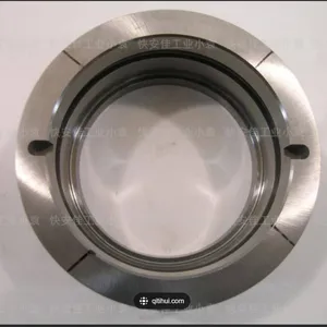
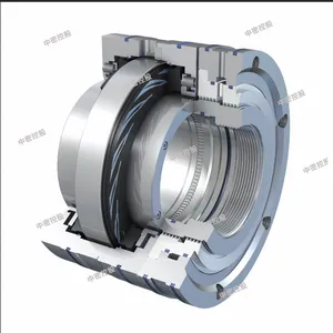
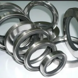
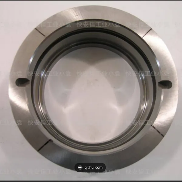
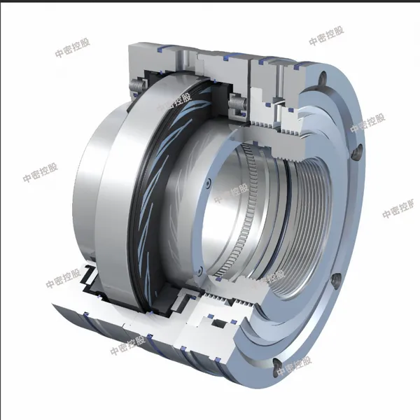
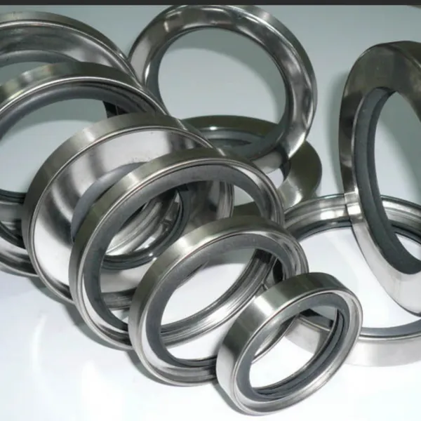
## I. Gas Seals: "Leakage-Proof Barriers" for Compressed Gases Installed between the compressor’s rotor journal and casing on the "gas side", gas seals (Gas Seals) have the core function of **preventing high-pressure gas in the compression chamber from leaking to the outside (external leakage) or stopping external air/impurities from entering the low-pressure chamber (internal leakage)**. They are key components ensuring compressor efficiency and safety. ### 1. Core Types and Technical Characteristics (Mainstream Industry Classifications) | Gas Seal Type | Structural Features | Working Principle | Application Scenarios | Advantages & Disadvantages | |---------------------|------------------------------------------------------|----------------------------------------------------------------------------------|-------------------------------------------------------|-------------------------------------------------------------| | Labyrinth Seal | Composed of "labyrinth teeth" on the rotor and a "seal body" on the casing, forming tortuous clearances | Reduces leakage through the "throttling effect" (gradual pressure reduction) when gas passes through narrow clearances; operates without contact | Medium-low pressure compressors (e.g., air compressors), clean gas media (e.g., nitrogen) | Advantages: No wear, long service life (8-12 years), low maintenance cost; Disadvantages: Relatively high leakage (usually 0.5%-2%) | | Dry Gas Seal | Consists of a rotating ring (rotates with the rotor) and a stationary ring (fixed), with micron-level grooves on the surface | Injects clean seal gas (e.g., nitrogen) to form a 5-10μm "gas film" for non-contact sealing; leaked gas is recovered | High-pressure, high-speed compressors (e.g., natural gas compressors, syngas compressors) | Advantages: Minimal leakage (≤0.1Nm³/h), high efficiency; Disadvantages: Requires supporting seal gas system (filtration, pressurization), high cost | | Carbon Ring Seal | Composed of 3-5 segmented graphite carbon rings and metal rings, pre-tensioned by springs | Carbon rings make slight contact with the journal; sealing is achieved via the self-lubricating property of graphite; leaked gas is recovered through labyrinths | Medium-high pressure compressors, gases with small amounts of impurities (e.g., chemical feed gas) | Advantages: Strong adaptability, impact resistance; Disadvantages: Carbon rings wear easily (service life 3-5 years), requiring regular replacement | ### 2. Key Technical Parameters (Core Basis for Selection) - **Leakage Rate**: A core indicator of sealing performance; typically ≤2% of rated flow for labyrinth seals, and ≤0.1Nm³/h for dry gas seals. - **Sealing Pressure Difference**: The maximum gas pressure difference a gas seal can withstand (e.g., dry gas seals can handle 10-20MPa, while labyrinth seals usually ≤5MPa). - **Operating Temperature**: Must match the compressor’s discharge temperature (e.g., carbon ring seals tolerate ≤300℃, dry gas seals ≤200℃). - **Adaptable Rotational Speed**: Matches the rotor’s linear speed (e.g., dry gas seals adapt to linear speeds ≤150m/s, with no strict limits for labyrinth seals). ### 3. Common Issues and Maintenance Points - Labyrinth Seals: "Tooth tip wear" (caused by rotor vibration) is common; regularly check clearances (normal value 0.1-0.3mm) and replace the seal body when wear exceeds limits. - Dry Gas Seals: Gas film rupture easily occurs due to "liquid carryover/impurities in seal gas"; ensure seal gas filtration precision ≤1μm and replace filter elements regularly. - Carbon Ring Seals: Graphite rings are prone to "cracking" (due to installation deviation); ensure proper alignment of segmented carbon rings and uniform spring pre-tension when replacing. ## II. Oil Seals: "Leakage-Proof Barriers" for Lubricating Oil Installed between the compressor’s rotor journal and bearing housing on the "lubricating oil side", oil seals (Oil Seals) have the core function of **preventing lubricating oil in the bearing housing from entering the gas chamber (avoiding gas contamination or reduced compression efficiency) and stopping external dust/moisture from entering the lubricating oil (preventing oil deterioration)**. They are key components ensuring the normal operation of the lubrication system. ### 1. Core Types and Technical Characteristics (Mainstream Industry Classifications) | Oil Seal Type | Structural Features | Working Principle | Application Scenarios | Advantages & Disadvantages | |-----------------------|------------------------------------------------------|----------------------------------------------------------------------------------|-------------------------------------------------------|-------------------------------------------------------------| | Lip Seal | Composed of a rubber lip (nitrile rubber/fluororubber) and a metal skeleton, secured to the journal by spring tension | The rubber lip makes tight contact with the journal (contact pressure 0.1-0.3MPa) to form a sealing surface, preventing oil leakage | Medium-low speed compressors (e.g., refrigeration compressors), normal-temperature working conditions | Advantages: Simple structure, low cost; Disadvantages: Lips wear easily (service life 1-2 years), prone to overheating at high speeds | | Oil Slinger Seal | Equipped with an "annular oil slinger" on the rotor and an "oil return groove" in the bearing housing | Uses centrifugal force to fling lubricating oil into the oil return groove; operates without contact, assisted by labyrinth seals for leakage prevention | High-speed compressors (e.g., turbine compressors), large-scale units | Advantages: No wear, long service life (synchronized with the rotor); Disadvantages: Requires precise oil level control (excessive oil causes leakage), large installation space | | Floating Ring Seal | Composed of 2-3 sets of metal floating rings (radially movable), sealed by an oil film | Lubricating oil enters the clearance (0.05-0.1mm) between floating rings and the journal to form an "oil film", balancing pressure differences and preventing oil leakage | High-pressure, high-speed compressors (e.g., ammonia synthesis compressors) | Advantages: Good sealing performance, high pressure resistance (≤15MPa); Disadvantages: Strict oil temperature control (40-60℃ required), prone to oil film failure | ### 2. Key Technical Parameters (Core Basis for Selection) - **Seal Lip Contact Pressure**: A core parameter for lip seals, typically 0.1-0.3MPa; insufficient pressure causes leakage, while excessive pressure accelerates wear. - **Lubricating Oil Viscosity**: Must match the oil seal material (e.g., nitrile rubber oil seals adapt to 20-100cSt, fluororubber to 100-300cSt). - **Operating Temperature**: Temperature resistance range (e.g., nitrile rubber: -30℃ to 120℃; fluororubber: -20℃ to 200℃). - **Rotor Journal Surface Roughness**: Affects sealing performance; typically requires Ra ≤0.8μm (to avoid scratching the lip). ### 3. Common Issues and Maintenance Points - Lip Seals: "Lip aging/cracking" (caused by high temperature/oil deterioration) is common; regularly check oil quality (acid value ≤0.5mgKOH/g) and replace promptly when aging occurs. - Floating Ring Seals: Friction between rings and the journal easily occurs due to "oil film interruption"; ensure stable lubricating oil pressure (usually 0.2-0.4MPa) and clean oil return holes regularly. - Oil Slinger Seals: "Excessive oil level" causing leakage is common; control the oil level at 1/2-2/3 of the oil gauge and check for oil return groove blockages. ## III. Core Differences Between Gas Seals and Oil Seals (Avoid Confusion) | Comparison Dimension | Gas Seals | Oil Seals | |----------------------|------------------------------------|------------------------------------| | Sealing Object | Compressed gases (e.g., air, natural gas, nitrogen) | Lubricating oil (e.g., turbine oil, gear oil) | | Installation Position| Between the compressor casing and journal (near the gas chamber side) | Between the bearing housing and journal (near the lubricating oil side) | | Core Risks | Gas leakage (causing efficiency loss, safety hazards) | Lubricating oil leakage (contaminating gas, oil deterioration) | | Media Compatibility | Must adapt to gas corrosiveness (e.g., Hastelloy seal bodies for acidic gases) | Must adapt to the chemical properties of lubricating oil (e.g., oil-resistant rubber materials) |

Send Inquiry to This Supplier


You May Also Like
-
 Centrifugal Compressor Turbine Compressor Circulating Supercharger Nitrogen Compression and Expansion MachineNegotiableMOQ: 1 Unit
 -
ImpellerUS$ 10000 - 20000MOQ: 1 Unit
-
Chemical Industry Refrigeration Energy IndustryUS$ 20000 - 300000MOQ: 1 Unit
-
Corrosion Resistant CrMo Pipe for Refinery and Chemical IndustryUS$ 0.6 - 1.5MOQ: 100 Kilograms
-
Industrial Spray Drying Equipment for Food, Pharmaceutical, Plastic Resin and Chemical IndustryNegotiableMOQ: 1 Set
-
Vertical Fireproof FRP Storage Tank for Chemical Industrial ApplicationsNegotiableMOQ: 1 Piece
-
Aerospace, Marine, Energy, and Chemical Industry Applications Supported by Nickel Alloy CoilUS$ 28.5 - 68.8MOQ: 100 Kilograms
-
Industrial Pneumatic V-Type Ball Valve With 304/316 Stainless Steel Body for Chemical IndustryNegotiableMOQ: 1 Set
-
High Impact Resistance BJ-CD Insulated CV Coupling For Steel Rolling & Chemical Industry EquipmentNegotiableMOQ: 1 Piece
-
Polytetrafluoroethylene Anticorrosive Pump for Chemical IndustryNegotiableMOQ: 1 Piece


