

Home > Industrial Equipment & Components > Valve > Gate Valve > Corrosion-Resistant Cast Iron & Stainless Steel Sluice Gate for Wastewater Treatment
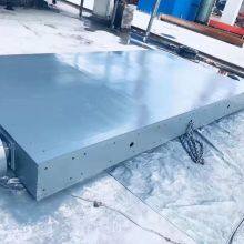
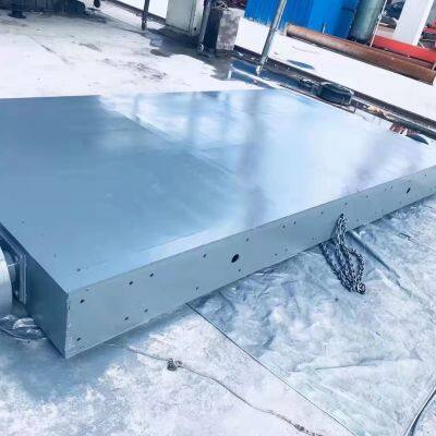
Corrosion-Resistant Cast Iron & Stainless Steel Sluice Gate for Wastewater Treatment


US$ 100 - 3000
MOQ: 10 Combos
Key Specifications
Get Latest Price
Material:
Steel
Type:
Right-angle
Application:
Water Industrial Usage
Payment & Shipping
Payment Methods:
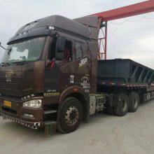
Port of Shipment:
Tianjin/Qingdao
Delivery Detail:
15 days
Related Products
-
 Arc-shaped Sluice Gate, River Water Diversion for Hydroelectric Power and IrrigationUS$ 550 - 690MOQ: 1 Combo
 -
Arc Gate Steel Gate, Arc Gate, Sewage Treatment Steel Gate, Reservoir Hydraulic Steel Gate ValveUS$ 550 - 690MOQ: 1 Combo
-
Arc Gate Sewage Treatment Hydropower Station Overflow Dam Discharge Steel Gate Reservoir Hydraulic Arc GateUS$ 550 - 690MOQ: 1 Combo
-
Manufacturer Supplies Curved Steel Sluice Gates, Sliding Steel Gates for Reservoirs and Rivers, and Double-leaf Steel Lifting Curved Gates.US$ 550 - 690MOQ: 1 Combo
-
Reservoir Gate Plane Sliding Fixed-wheel Type Curved Steel Gate Hydraulic Engineering River Steel Solid Manufacturer in StockUS$ 550 - 690MOQ: 1 Combo
Material
Steel
Type
Right-angle
Application
Water Industrial Usage
Usage
Drain, Flow Control
Standard
Other, ISO9001
Actuator
Electric
Seal Surface
Parallel Gate Valve
Thread Position of Valve Rod
Inside Gate Valve
Media
Water
Temperature
High Temperature
Pressure
Ordinary Pressure
Connection Form
Thread
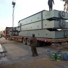
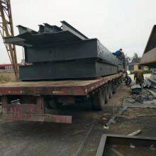
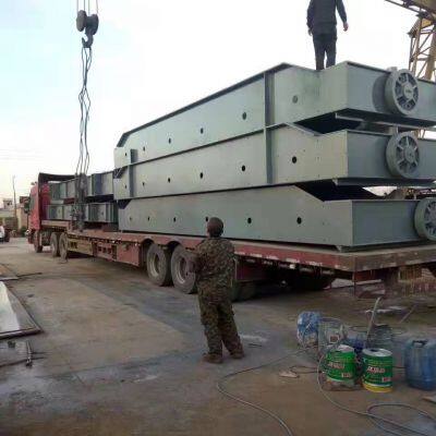
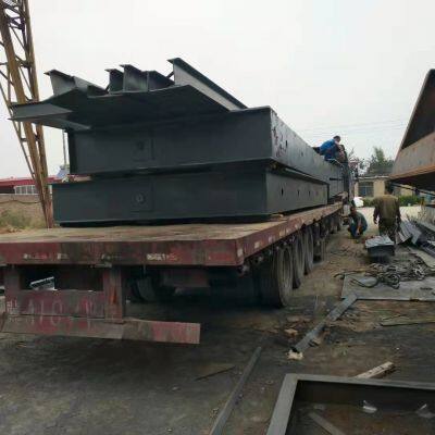
Transport Package
Wooden packaging
Specification
Custom made according to the drawings
Trademark
HaoGu
Origin
HeBei
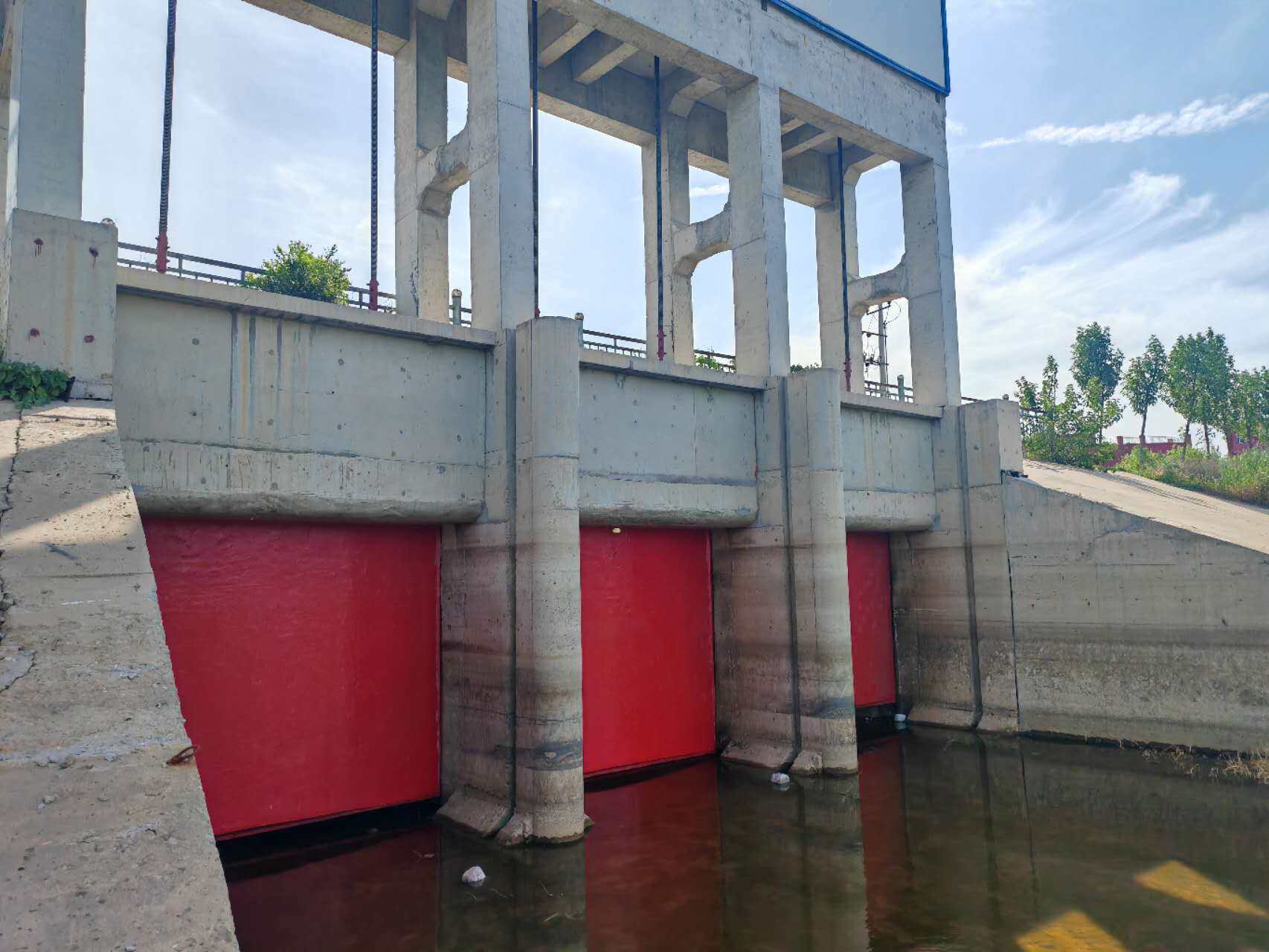
Installation Process of Steel Sluice Gates
Steel sluice gates are critical components in water management systems, including dams, reservoirs, irrigation canals, and wastewater treatment plants. Their installation requires meticulous planning, precision engineering, and adherence to safety and industry standards to ensure structural integrity, operational efficiency, and long-term durability. Below is a detailed, step-by-step guide to the installation process of steel sluice gates.
1. Pre-Installation Planning and Preparation
Before commencing physical installation, thorough planning is essential to mitigate risks and ensure alignment with design specifications.
2. Positioning and Alignment of the Gate Frame
The gate frame serves as the structural anchor for the gate leaf, guiding its opening/closing movement and ensuring a watertight seal. Precise alignment is critical to avoid binding, leakage, or premature wear.
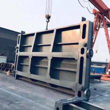
3. Installation of the Gate Leaf
The gate leaf—the movable barrier that controls water flow—is the heaviest component, requiring careful handling to avoid deformation or damage.
4. Integration of Operating Mechanisms
Steel sluice gates are operated manually (handwheels, levers) or mechanically (electric motors, hydraulic cylinders, pneumatic systems). Integrate the operating mechanism with the gate leaf for precise control.
5. Corrosion Protection and Finishing
Steel gates are vulnerable to corrosion (especially in aquatic environments), so post-installation protective measures are critical.
6. Testing and Commissioning
Before final acceptance, conduct rigorous testing to verify performance, safety, and compliance with design standards.
7. Documentation and Handover
Upon successful testing, compile comprehensive documentation:
Conduct a handover meeting with the client, provide training on operation and basic maintenance, obtain final approval, and commission the gate for regular use.
In summary, installing a steel sluice gate is a multi-stage process that demands technical expertise, precision, and adherence to safety and quality standards. Each step—from planning to testing—plays a critical role in ensuring the gate operates reliably for decades, even in harsh aquatic environments.

Send Inquiry to This Supplier

* Email
Want the best price?
Post an RFQ now!

1Yr
Year Established
2025
Factory Size
3,000-5,000 square meters
Annual Export Value
US$5 Million - US$10 Million
Total Employees
51 - 100 People
You May Also Like
-
Pulley-type Curved Steel Gate, Large Reservoir Steel Gate, Wastewater Treatment Steel Gate, Double-leaf GateUS$ 550 - 690MOQ: 1 Combo
-
Steel Gate Manufacturer, River Flood Control, Stainless Steel Water-stop and Flood Discharge, Large Flat Sliding Arc Steel Dam EquipmentUS$ 1000 - 1150MOQ: 1 Combo
-
Flat Sliding Fixed-wheel Curved Steel Sluice Gate Hydraulic Engineering Channel River Steel ManufacturerIn-stock ReservoirUS$ 1000 - 1150MOQ: 1 Combo
-
Steel Sluice Gate, Hydraulic Curved Steel Sluice Gate Manufacturer, Reservoir Switch, Power Station Stainless Steel Sluice ValveUS$ 1000 - 1150MOQ: 1 Combo
-
Steel Sluice Gate Channel, Steel Electric Sluice Gate, Curved Hydraulic Steel Gate, Manufacturer, Reservoir Stainless Steel Regulating Weir GateUS$ 1000 - 1150MOQ: 1 Combo
-
Cast Iron Sluice Gate, Curved Cast Iron Sluice Gate, Source Manufacturer for Hydraulic Engineering Construction, Available in Various SpecificationsUS$ 1000 - 1150MOQ: 1 Combo
-
Hydraulic Lifting Steel Dam Gate Factory Curved Stainless Steel and Carbon Steel Dam Flat Sliding Fixed Wheel Flap Floodgate ReservoirUS$ 1000 - 1150MOQ: 1 Combo
-
Arc-shaped Sluice Gate Engineering Channel Gate Machine Cast Iron Reservoir Steel Integrated Manual Water-stopping Square Solid FactoryUS$ 1000 - 1150MOQ: 1 Combo
-
Planar Sliding Fixed-wheel Arched Steel Sluice Gate for Hydraulic Engineering Channels and River Steel GatesUS$ 1000 - 1150MOQ: 1 Combo
-
Arc-shaped Steel Sluice Gate Channel for Water Conservancy and Farmland Regulation, Bidirectional Watertight Shut-off and DrainageUS$ 1000 - 1150MOQ: 1 Combo


