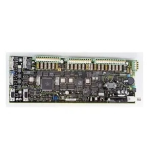
Material
Other, Global universal model
Condition
Other, Global universal model
Task
Other, Global universal model
Mathematical Model
Other, Global universal model
Signal
Other, Global universal model
Customized
Non-Customized
Structure
Other, Global universal model
Operating Temperature
-20℃-60℃
Relative Humidity
10%-90% (non-condensing)
Storage temperature
-40℃-85℃
Dimensions
120mm × 180mm × 70mm
I. Overview
The ABB UNS0880A-P,V1 3BHB005922R0001 is a safety bus communication module launched by ABB in the field of industrial automation. Its core positioning is a "high-reliability data interaction bridge between Industrial Safety Instrumented Systems (SIS) and distributed safety equipment". Its core value lies in establishing a hierarchical safety data transmission network of "safety controller - distributed safety I/O - on-site safety instruments" through SIL 2 safety certification and a redundant bus architecture. It provides an integrated communication solution of "long-distance safety signal transmission + fault isolation + redundant backup" for industries with extremely high requirements for real-time performance and reliability of safety data transmission, such as petrochemicals, electric power, and metallurgy. This ensures the delay-free and error-free interaction of safety interlock commands (e.g., emergency shutdown, valve cut-off) and equipment status signals (e.g., sensor alarms, actuator feedback) in industrial processes, and prevents safety accidents caused by communication link failures.
Compared with conventional industrial bus modules, it focuses more on "in-depth adaptation of safety buses and compatibility with distributed scenarios":
Specifically designed for the ABB System 800xA SIS and PROFIBUS PA safety bus, it supports the cascaded expansion of distributed safety I/O modules (such as the ABB IM153-4 PN/S), enabling safety data acquisition and control for up to 32 distributed nodes.
At the same time, it adopts an industrial-grade wide-temperature and strong anti-interference design, allowing stable operation in harsh workshop environments with dust, electromagnetic interference, and temperature fluctuations.
As a core communication component of ABB's distributed safety system, it enables bus-based connection between safety controllers and long-distance on-site equipment (replacing traditional point-to-point wiring), reducing on-site wiring costs and complexity. It also supports node-level fault isolation (a single node failure does not affect the overall bus communication), making it a key hardware support in the industrial field for "realizing distributed safety control and improving system flexibility and reliability".
II. Technical Parameters
(I) Communication Performance Parameters
(II) Safety and Redundancy Parameters
(III) Environmental and Physical Parameters
(IV) Power Supply and Interface Parameters

III. Functional Features
(I) Optimized Safety Bus Design for Distributed Safety Control
Long-distance safety data transmission: The fixed rate of 31.25kbps and 1900m non-repeater transmission distance of the PROFIBUS PA protocol are suitable for long-distance distributed scenarios in large factories (e.g., safety monitoring of multiple reactors in a petrochemical park, distributed valve control in a power plant area). It replaces traditional point-to-point wiring (reducing on-site wiring by 80%), lowering construction costs and post-maintenance difficulty.
Multi-node cascaded expansion: Supports cascading of 32 slave nodes, and each node can be connected to distributed safety I/O modules (such as the ABB IM153-4 PN/S), enabling the construction of a large-scale distributed safety system with "1 master module + 32 slave nodes". For example, in a metallurgical workshop, the master station is installed in the central control room's SIS cabinet, and 32 slave stations are deployed in each rolling mill area to collect temperature and pressure signals and control emergency shutdown valves, realizing the combination of centralized monitoring and distributed control.
(II) Dual Redundancy and Fault Isolation for Improved System Reliability
Dual-bus and power redundancy: The dual-bus redundancy design (main bus for normal communication, backup bus for real-time data synchronization) enables switching to the backup bus within 10ms when the main bus fails due to disconnection or short circuit, ensuring uninterrupted communication. Dual power redundancy ensures that the backup power supply takes over within 5ms when the main power supply is cut off, avoiding safety risks caused by communication interruptions (e.g., failure to issue emergency shutdown commands).
Node-level fault isolation: When a single slave node (e.g., a distributed I/O module) fails, the module automatically disconnects the node from the bus through internal logic (similar to a "circuit breaker" function), allowing other nodes to communicate normally. For example, if a slave station goes offline due to electromagnetic interference, the module isolates the node, and the remaining 31 nodes can still transmit data normally. Maintenance personnel can troubleshoot without affecting production, improving system availability.
(III) Industrial-Grade Environmental Adaptability for Stable Operation
Wide temperature range and strong anti-interference: The operating temperature range of -20℃-60℃ covers unheated workshops in northern winters (-15℃) and high-temperature workshops in southern summers (55℃). The anti-interference capabilities of ±8kV ESD contact discharge and ±4kV EFT electrical fast transient can resist electromagnetic interference generated by workshop motors and frequency converters, ensuring a bus communication data error rate ≤10⁻⁹, which is far lower than the industrial-grade requirement of 10⁻⁶.
Dust and corrosion resistance: Interface terminals adopt an anti-oxidation gold-plated design, which can resist corrosion from corrosive gases (e.g., hydrogen sulfide, chlorine gas) and dust in chemical workshops. The terminal contact resistance is ≤10mΩ, extending the maintenance cycle to 18 months. PROFIBUS PA interfaces are equipped with dust covers to prevent dust from entering and protect interface contacts when not in use.
(IV) Usability and Flexible Configuration for Lowered Application Thresholds
Simplified bus configuration: Parameter configuration is performed via ABB Control Builder M software, which has a built-in "PROFIBUS PA safety bus configuration template". Engineers only need to import the GSD file (device description file) of the slave station equipment to automatically identify the slave station model and I/O channels, without manually writing bus protocol code. Basic configuration for 32 slave stations can be completed within 30 minutes.
Dual installation adaptation: Supports ABB standard rack mounting (integrated into the System 800xA SIS) and independent DIN rail mounting (deployed in distributed control cabinets). For example, in a remote oil wellhead, the module is installed in the wellhead's local control cabinet via DIN rails and communicates with the SIS in the central control room 5km away via the PROFIBUS PA bus, enabling safety monitoring of wellhead pressure and temperature without building a complex control room at the wellhead.
(V) Fault Diagnosis and O&M Optimization for Enhanced Efficiency
Visual fault feedback: The module panel is equipped with three levels of LED indicators (power, bus, and node), allowing maintenance personnel to quickly locate the fault level through the indicators. For example, a "yellow light on the main bus" indicates a main bus fault, and a "red light on slave stations 1-8 group" indicates a faulty node in the group. Meanwhile, fault information (including fault type, occurrence time, and affected nodes) can be exported via the USB interface or upper-level system (System 800xA HMI), facilitating fault cause tracing.
Local and remote debugging: The USB Type-C interface supports local debugging with a laptop, allowing engineers to check the bus load rate (normal ≤60%), slave station communication status (online/offline), and data transmission rate on-site. For long-distance sites, the module can be accessed remotely via the PROFIBUS DP interface to modify bus parameters (e.g., repeater configuration) and upgrade firmware, reducing fault handling time from 4 hours to 1 hour.
IV. Application Fields
(I) Petrochemical Industry: Distributed Reactor Safety Monitoring
Application Scenario
Ten distributed propylene reactors in a large refinery (distributed within 500-1500m of the plant area) require: 1. Safety signal acquisition (temperature, pressure, and emergency stop button signals of each reactor); 2. Safety interlock control (cut off the feed valve and open the safety valve when temperature >85℃ or pressure >2.2MPa); 3. Bus communication (replacing point-to-point wiring to reduce on-site construction workload). The environment is a chemical park (temperature 15-45℃, with propylene vapor, strong electromagnetic interference, and heavy dust).
Module Function Implementation
Bus architecture construction: One ABB UNS0874A-P, V1 module is used as the master station, installed in the SIS cabinet of the central control room and connected to the System 800xA SIS controller; ten ABB IM153-4 PN/S distributed safety I/O modules are used as slave stations, deployed in the on-site control cabinets of the ten reactors respectively, and cascaded via the PROFIBUS PA bus in a daisy-chain manner (total distance ≤1500m, no repeater required).
Signal acquisition and interlocking: Each slave station is connected to 2 temperature RTDs (Pt100), 2 pressure transmitters (4-20mA), and 1 emergency stop button (DI), and uploads signals to the master station via the bus. After receiving the signals, if the temperature of a reactor exceeds 85℃ or the pressure exceeds 2.2MPa, the master station immediately issues commands to the corresponding slave station via the bus: "cut off the feed valve (DO output 4mA) and open the safety valve (DO output 20mA)". The response time is ≤50ms, preventing overpressure explosion of the reactor.
Fault handling: If the bus interface of the 5th slave station has poor contact due to dust, the master station detects the "Slave Station 5 Offline" fault, automatically isolates the node (the other 9 slave stations communicate normally), and triggers an alarm via the HMI. Maintenance personnel carry a laptop to the site, check the fault code "E01 - Slave Station 5 Offline" via the master station's USB interface, and after cleaning the slave station interface, the slave station automatically reconnects to the bus to resume communication without shutdown.
(II) Electric Power Industry: Distributed Valve Safety Control in Power Plants
Application Scenario
Twenty distributed steam valves in a 2×600MW thermal power plant (distributed in the boiler, steam turbine, and condenser areas, 300-1000m away from the central control room) require: 1. Valve status monitoring (switch feedback, fault alarm signals); 2. Safety interlock control (close the corresponding valve when steam pressure >14MPa); 3. Wiring reduction (replacing traditional point-to-point cables to reduce costs). The environment is a power plant area (temperature 0-55℃, with strong electromagnetic interference from motors and frequency converters, and heavy dust).
Module Function Implementation
Bus configuration: The master module (UNS0874A-P, V1) is installed in the Advant OCS ESD cabinet of the central control room; 20 slave stations (Siemens ET 200SP F safety I/O modules) are deployed in the on-site control cabinets of each valve, connected via the PROFIBUS PA bus (total distance ≤1000m, with 1 repeater to extend the distance); each slave station is connected to 2 valve switch feedbacks (DI), 1 valve fault signal (DI), and 1 valve control output (DO).
Interlock control: The master station collects valve status signals from slave stations in real-time via the bus and uploads them to the ESD controller. When the boiler steam pressure exceeds 14MPa (AI signal connected to the master station), the controller issues a "close the boiler outlet valve" command to the corresponding slave station, and the slave station's DO output signal drives the valve to close with a response time ≤60ms. Meanwhile, the master station feeds back the valve closure status to the controller via the bus to form closed-loop control.









 Contact Platform Support
 Help Center