Home > Electrical & Electronics > Electrical Control System > Metso Valmet A413177 Verification Module
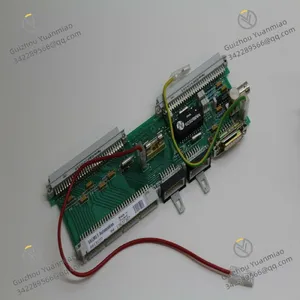
Metso Valmet A413177 Verification Module
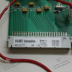
Metso Valmet A413177 Verification Module photo-1
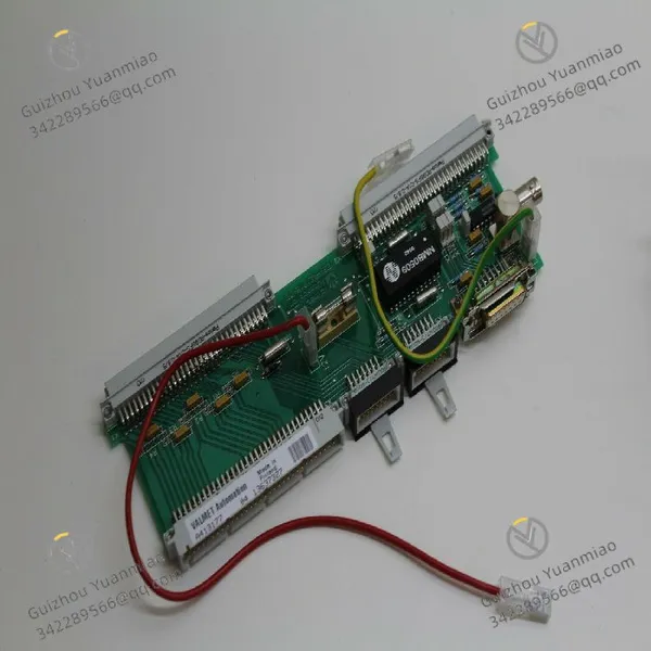
Metso Valmet A413177 Verification Module photo-2
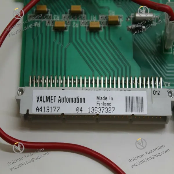
Negotiable MOQ: 1 Piece (Price negotiable depending on order volume and customization)
Key Specifications
Get Latest Price
Material:
Other, Global universal model
Condition:
Other, Global universal model
Task:
Other, Global universal model
Payment & Shipping
Payment Methods:
Port of Shipment:
guizhou
Delivery Detail:
Delivery time depends on order quantity.
Material Other, Global universal model
Condition Other, Global universal model
Task Other, Global universal model
Mathematical Model Other, Global universal model
Signal Other, Global universal model
Customized Non-Customized
Structure Other, Global universal model
Operating Temperature -25°C ~ 70°C
Relative Humidity 5%~95% (non-condensing)
Supply Voltage 24V DC ±15%
Dimensions 140mm × 90mm × 55mm

I. Overview


The Metso A413177 is an industrial-grade signal conversion and control interface module, primarily designed to be compatible with the control systems of Metso crushing and screening equipment (such as jaw crushers, cone crushers, vibrating screens, etc.). It undertakes the core functions of "on-site sensor signal acquisition - standard signal conversion - controller command transmission". Its design focuses on "high anti-interference performance" and "signal stability" for heavy-duty industrial scenarios, and adopts an isolated digital/analog signal processing architecture. This effectively suppresses mechanical vibrations, dust interference, and strong electromagnetic radiation in crushing workshops, making it widely used in industries that rely on large-scale crushing equipment, such as mining, building materials, and metallurgy.


Compared with general-purpose industrial interface modules, this module features "compatibility with Metso equipment-specific protocols", "wide temperature and voltage adaptability", and "fault self-diagnosis". It can be directly integrated into Metso C100/C200 series control cabinets, enabling seamless connection with the crusher's main controller, motor driver, and liquid level/pressure sensors. This ensures signal synchronization for critical operations such as equipment start-stop and load adjustment.


A413177 (2)


II. Technical Parameters


  1. Basic Specifications


Item Parameter Details
Overall Dimensions 140mm (Length) × 90mm (Width) × 55mm (Height) (DIN rail-compatible design)
Weight Approximately 0.3kg
Operating Temperature Range -25°C ~ 70°C (operation); -40°C ~ 85°C (storage)
Protection Level IP20 (installed inside the cabinet, dust-proof)
Installation Method 35mm standard DIN rail mounting


2. Electrical Performance

Power Supply Parameters:

  • Supply Voltage: 24V DC ±15% (compatible with DC power supplies commonly used in industrial equipment);

  • Rated Power Consumption: ≤5W (no-load); ≤12W (full-load signal processing);

  • Power Isolation: Input-output isolation voltage of 1500V AC (for 1 minute, preventing power crosstalk).


Signal Input Characteristics:

  • Digital Input: 8 channels, supporting NPN/PNP bipolarity (compatible with proximity switches, limit switches);

  • Analog Input: 4 channels, supporting 4-20mA current signals (compatible with pressure, liquid level, temperature sensors);

  • Input Impedance: Digital input ≥10kΩ; Analog input ≤250Ω.


Signal Output Characteristics:

  • Digital Output: 6 channels, relay output (contact rating: 2A/250V AC or 3A/30V DC);

  • Analog Output: 2 channels, 4-20mA current signals (load impedance: 0-500Ω);

  • Output Accuracy: Analog output error ≤±0.2% FS (at 25°C ambient temperature).


Communication Interface:

  • Interface Type: RS485 (half-duplex);

  • Supported Protocols: Modbus RTU (compatible with Metso equipment-specific sub-protocols);

  • Communication Baud Rate: 9600bps ~ 115200bps (configurable via DIP switches);

  • Address Range: 1-247 (slave address set via DIP switches).


3. Environmental Adaptability Parameters

Item Parameter Requirements
Vibration Resistance

Complies with IEC 60068-2-6 standard, 10-500Hz with 2g acceleration (10min/axis continuously)


Shock Resistance

Complies with IEC 60068-2-27 standard, 10g acceleration (11ms duration, 3 times per axis for 3 axes)


Humidity Tolerance


5%-95% RH (no condensation, at 25°C ambient temperature)


Electromagnetic Compatibility (EMC) Radiated Emission: EN 61000-6-4 Class A; Immunity: EN 61000-6-2 (ESD ±8kV contact / ±15kV air)


III. Functional Features


1. Multi-Type Signal Compatibility and Conversion

  • Full-Scenario Signal Coverage: It supports 8-channel digital input, 4-channel analog input, 6-channel relay output, and 2-channel analog output simultaneously. It can integrate "status detection sensors" (e.g., bearing temperature, hydraulic oil level) and "actuator control signals" (e.g., feeder start-stop, hydraulic valve adjustment) of the crusher in one stop. No additional modules are required, simplifying wiring;

  • Bipolar Digital Input Adaptation: The digital input supports NPN/PNP bipolarity, eliminating the need for manual hardware jumper switching. It is compatible with sensors of different brands (such as Omron and Pepperl+Fuchs proximity switches), reducing the difficulty of on-site selection and replacement.


2. Anti-Interference Design for Heavy-Duty Industry

  • Multi-Layer Isolation Protection: Triple electrical isolation (power supply - input - output) with an isolation voltage of 1500V AC. It can effectively block the interference of surge voltage and electromagnetic radiation generated by the start-stop of the crusher motor on signals, avoiding analog acquisition distortion (e.g., pressure signal fluctuation) or false triggering of digital signals (e.g., false alarm of "limit switch activation");

  • Wide Temperature and Vibration Resistance Optimization: The -25°C~70°C wide temperature design is suitable for alpine/high-temperature workshops in the mining industry. The shell is made of reinforced plastic material, and internal components adopt an anti-loosening fixed structure, which can withstand the high-frequency vibration environment during the operation of crushing equipment (e.g., 2g acceleration vibration during the operation of vibrating screens).


3. Convenient Operation & Maintenance and Fault Diagnosis

  • Visual Status Indication: 22 LED indicators are installed on the front - power indicator (green, constant on indicates normal power supply), input signal indicators (8-channel digital / 4-channel analog, lit indicates signal access), output signal indicators (6-channel relay / 2-channel analog, lit indicates output activation), and communication indicator (red, flashing indicates normal communication). The signal flow status can be quickly judged without an oscilloscope;

  • Fault Self-Diagnosis Function: Built-in fault detection circuit. When "power overvoltage/undervoltage", "analog input overrange", or "relay output short circuit" occurs, it will send fault codes to the main controller via RS485 (e.g., E01 indicates power fault, E05 indicates analog input overrange), and at the same time trigger the red alarm light to stay on, shortening the fault location time.


4. Exclusive Adaptation for Metso Equipment

  • In-Depth Protocol Compatibility: Supports Metso equipment-specific Modbus sub-protocols, and can directly communicate with Metso C100 crusher controller and TP150 operation panel. No additional communication driver programming is required, enabling seamless data interaction among "sensor data - controller - operation panel" (e.g., real-time display of crusher feed port pressure, remote adjustment of feed rate);

  • In-Cabinet Integration Optimization: Its size is adapted to the layout of Metso standard control cabinets. The DIN rail mounting method is compatible with other Metso modules (such as power modules and relay modules), enabling modular stacked installation and reducing space occupation inside the cabinet.


A413177 (1)


IV. Common Faults and Troubleshooting Methods


Fault Phenomenon Possible Causes Troubleshooting Measures
Power indicator not on, no signal response
  1. 24V DC power not connected / abnormal voltage (<20.4V or >27.6V); 2. Loose wiring at power terminals / broken cable; 3. Burnt internal power circuit of the module


  1. Use a multimeter to detect the supply voltage and confirm it is within the range of 24V DC ±15%; 2. Check the wiring of power terminals (+V/-V), re-tighten the screws, and replace the broken cable; 3. If there is still no response when the power supply is normal, replace the module with the same model (burnt internal power circuit is mostly irreversible)


No analog input data (corresponding input indicator not on) 1. Sensor not powered / faulty sensor; 2. Broken analog input cable / reversed positive and negative poles; 3. Input signal overrange (>20mA or <4mA); 4. Burnt input channel of the module
  1. Detect the sensor power supply (e.g., 24V DC) and replace the faulty sensor; 2. Use the continuity function of a multimeter to detect the input cable, and re-wire (ensure the positive and negative poles of 4-20mA are correct); 3. Confirm that the sensor measurement range matches the module input range (e.g., pressure sensor range 0-10MPa corresponds to 4-20mA); 4. Replace with a spare input channel (e.g., switch the signal of Channel 1 to Channel 2). If all channels have no response, return the module to the factory for repair


No relay output action (corresponding output indicator not on) 1. Main controller not sending output commands (e.g., Modbus command not issued); 2. Loose wiring at output terminals / burnt relay contacts; 3. Output short circuit triggering internal protection of the module
  1. Check whether the output command is issued via the Metso TP150 operation panel, or use a serial port debugging tool to read the module register (confirm whether the output command bit is "1"); 2. Re-tighten the wiring of output terminals, and use the resistance function of a multimeter to detect the relay contacts (normally open when not activated, short-circuited after activation; if always open, the contacts are burnt, and the module needs to be replaced); 3. Disconnect the load at the output end, restart the module to release the protection, and check whether the load is short-circuited (e.g., short-circuited solenoid valve coil)


Communication interruption (communication indicator not flashing) 1. RS485 cable not properly connected / reversed positive and negative poles (A/B wires reversed); 2. Mismatched communication baud rate / slave address with the main controller; 3. Communication cable affected by electromagnetic interference (unshielded cable used); 4. Burnt communication port of the module
  1. Check the RS485 cable (A connected to A, B connected to B) and re-plug the wiring; 2. Adjust the communication baud rate (e.g., 9600bps) and slave address (e.g., 05) via the module's DIP switches to ensure consistency with the main controller parameters; 3. Replace the RS485 cable with a shielded layer, and ground one end of the shielded layer (connect to the control cabinet ground bar); 4. Replace with a spare communication module (if available), or return the module to the factory for communication port repair


Red alarm light stays on (accompanied by fault code) 1. Power overvoltage/undervoltage (triggering code E01); 2. Analog input overrange (triggering code E05); 3. Relay output short circuit (triggering code E10)
  1. Detect the supply voltage and resolve power grid fluctuations (e.g., install a regulated power supply); 2. Check the corresponding analog input signal (e.g., whether the pressure sensor is overloaded) and adjust the sensor measurement range; 3. Disconnect the load at the faulty output end, check and resolve the short-circuit fault (e.g., replace the short-circuited solenoid valve), and restart the module to clear the alarm


False triggering of digital input (corresponding input indicator flashing frequently) 1. Excessive on-site electromagnetic interference (e.g., close to high-power motors); 2. Unshielded cable used for digital input; 3. Poor grounding of the module 1. Keep the input cable away from high-power motors (e.g., distance ≥1m); 2. Replace the digital input cable with a shielded layer and ground the shielded layer; 3. Check whether the module's grounding terminal (GND) is reliably grounded (ground resistance ≤4Ω) and re-tighten the grounding screws
Product Tags: A413177

Send Inquiry to This Supplier

* Message
0/5000

Want the best price? Post an RFQ now!
Verified Business License
Business Type
Trading Company
Year Established
2014
Factory Size
1,000-3,000 square meters
Product Certifications
SA8000