



Home > Electrical & Electronics > Electrical Control System > GE DS2020PDMAG6 Power Distribution Module
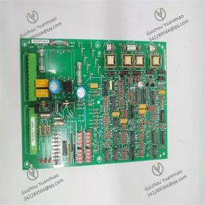
GE DS2020PDMAG6 Power Distribution Module
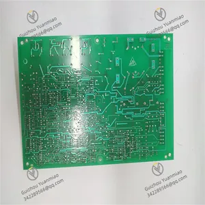
GE DS2020PDMAG6 Power Distribution Module photo-1
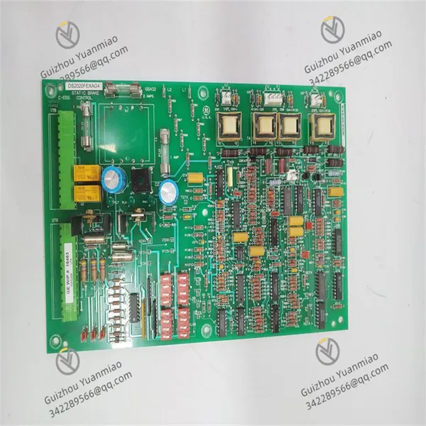
GE DS2020PDMAG6 Power Distribution Module photo-2
Negotiable MOQ: 1 Piece (Price negotiable depending on order volume and customization)
Key Specifications
Get Latest Price
Material:
Other, Global universal model
Condition:
Other, Global universal model
Task:
Other, Global universal model
Payment & Shipping
Payment Methods:
Port of Shipment:
China
Delivery Detail:
Delivery time depends on order quantity.
Material Other, Global universal model
Condition Other, Global universal model
Task Other, Global universal model
Mathematical Model Other, Global universal model
Signal Other, Global universal model
Customized Non-Customized
Structure Other, Global universal model
Power Supply 24V DC
Operating Temperature 0℃ - 50℃
Dimensions 160mm×233mm×20mm
  1. Overview


GE DS2020PDMAG6 is a power distribution module specifically designed for the Mark V steam turbine control system, playing a core role in power distribution and management within the entire control system. It is mainly applied to equipment driven by various industrial steam turbines, such as steam turbine generator sets in power plants and large compressor-driven steam turbines in the petrochemical industry. It provides reliable power support for the stable operation of these critical pieces of equipment.


The core mission of this module is to accurately and efficiently distribute the input electrical energy to various sub-modules and components of the steam turbine control system, ensuring that different components receive stable and suitable power supply. Through scientific and reasonable power distribution, it maintains the coordinated operation of all links in the control system, thereby ensuring the stable operation of the steam turbine and avoiding equipment failures or operational fluctuations caused by power anomalies.


DS2020PDMAG6 features excellent reliability and stability. It adopts high-quality electrical components, which can effectively resist adverse factors such as electrical interference and voltage fluctuations in complex and changing industrial environments, and always maintain stable power distribution performance, laying a solid foundation for the long-term and reliable operation of the steam turbine control system. Meanwhile, it adheres to the standardized design concept of the Mark V product series and has excellent compatibility with other modules in the same series, facilitating system integration and expansion to meet the actual needs of industrial projects of different scales.


DS2020FEXAG4 (2)


2. Technical Parameters


  • Power Input: Supports multiple common industrial voltage input specifications. The main rated input voltage is 220V AC, with an allowable voltage fluctuation range of ±10%, which can adapt to minor differences in different power supply environments. The frequency range is 47Hz - 53Hz, which is compatible with the industrial power grid frequencies in most regions around the world, ensuring stable operation when used in different geographical locations. The input current capacity depends on the actual load conditions, which can meet the power requirements of various components in the Mark V steam turbine control system and has strong load-bearing capacity.

  • Output Parameters: It can provide stable DC voltage output in multiple channels. Common output voltages include +5V DC, ±12V DC, +24V DC, etc., to meet the diverse power needs of different sub-modules and components. The accuracy of each output voltage is controlled within ±0.5%, which can ensure the stability of the output voltage and avoid adverse effects on the normal operation of equipment due to excessive voltage deviation. In terms of output current, each channel can provide the corresponding rated current according to the type and quantity of connected loads. For example, the +5V DC output channel can provide a maximum current of 3A, the ±12V DC output channel can provide a maximum current of 1A, and the +24V DC output channel can provide a maximum current of 2A, meeting the power needs of equipment with different power levels.

  • Electrical Performance: It has excellent overcurrent protection capability. When the output current exceeds 120% - 150% of the rated value, the protection circuit will act quickly to cut off the output, preventing damage to the module and downstream equipment caused by overcurrent. It also has an overvoltage protection function. When the input voltage or output voltage exceeds the normal range, it can automatically limit the voltage to avoid damage to the equipment caused by excessive voltage. The module has a high conversion efficiency of 85% - 90%, which not only distributes power efficiently but also effectively reduces its own power consumption, minimizes energy waste, and improves the overall energy efficiency of the system.

  • Communication Interface: Equipped with an RS485 communication interface and adopting the Modbus RTU communication protocol, it facilitates data interaction with upper-level computer control systems or other intelligent devices. Through this interface, the module's operating status information (such as input/output voltage, current value, fault alarm information, etc.) can be uploaded in real time, and control commands issued by the upper-level computer (such as remotely turning on or off certain output channels) can also be received, realizing remote monitoring and management and improving operation and maintenance efficiency. The communication rate can be configured among common rates such as 9600bps, 19200bps, and 38400bps to adapt to the communication needs of different industrial sites.

  • Operating Environment: The operating temperature range is 0℃ - 50℃, which can adapt to temperature changes in most industrial sites and operate stably whether in hot summers or cold winters. The relative humidity range is 5% - 95% (non-condensing), allowing normal operation in humid environments and reducing the risk of electrical faults caused by environmental humidity issues. The protection level reaches IP20, which can effectively prevent the intrusion of dust and foreign objects with a diameter greater than 12.5mm, making it suitable for relatively clean installation environments such as indoor control cabinets.

  • Physical Dimensions: Adopts a standard 6U high VME board design, with dimensions of 160mm in height, 233mm in width, and 20mm in thickness. The compact size facilitates installation in various control cabinets and system frameworks, saving installation space, which is conducive to the miniaturization and integrated layout of the system and makes it easy to form a complete steam turbine control system together with other modules.


3. Functional Features


  • Accurate Power Distribution: Relying on advanced circuit design and precise voltage regulation technology, GE DS2020PDMAG6 can accurately convert the input AC power into DC power that meets the needs of various components of the steam turbine control system and stably distribute it to each power-consuming unit. Its output voltage has extremely high accuracy, which effectively avoids adverse effects on equipment performance caused by voltage fluctuations or uneven distribution, ensuring that all parts of the control system operate under optimal power conditions and providing a solid power foundation for the stable and efficient operation of the steam turbine.

  • Multiple Protection Mechanisms: This module has built-in comprehensive overcurrent, overvoltage, undervoltage, and short-circuit protection functions. Once abnormal electrical conditions are detected, the protection circuit will respond quickly, cut off the relevant output in a timely manner, or take current-limiting and voltage-limiting measures to prevent damage to the module itself and downstream equipment due to electrical faults. This all-round protection mechanism greatly improves the reliability and stability of the system, reduces the probability of equipment failures caused by power issues, minimizes maintenance costs and downtime, and ensures the continuity of industrial production.

  • Convenient Communication and Monitoring: With the RS485 communication interface and Modbus RTU communication protocol, DS2020PDMAG6 can easily achieve seamless connection with the upper-level computer monitoring system. Operation and maintenance personnel can obtain various operating parameters and status information of the module in real time through monitoring software, such as input/output voltage and current, module temperature, and working mode, making it easy to grasp the equipment operating status in a timely manner. At the same time, they can also remotely configure parameters and perform control operations on the module, such as adjusting the output voltage and turning on or off specific output channels, realizing remote monitoring and management, improving operation and maintenance efficiency, and reducing labor costs.

  • High Reliability and Stability: During the design and manufacturing process, GE DS2020PDMAG6 uses high-quality industrial-grade components and undergoes strict quality inspection and reliability testing. These components have good electrical performance and anti-interference capabilities, enabling stable operation in complex industrial electromagnetic environments. In addition, the circuit design of the module fully considers factors such as heat dissipation and lightning protection, further enhancing its reliability and stability, allowing it to adapt to long-term and high-load industrial operating environments and providing reliable support for the long-term and stable operation of the steam turbine control system.

  • Excellent System Compatibility: As part of the Mark V steam turbine control system, DS2020PDMAG6 has excellent compatibility with other modules in the series, such as control modules, signal acquisition modules, and communication modules. It can work in coordination with these modules to build a complete and efficient steam turbine control system. Meanwhile, the standardized design of the module makes it easy to reuse and expand in different projects. Whether it is a new project or the upgrading and transformation of an existing system, it can be easily adapted, reducing the difficulty and cost of system integration.

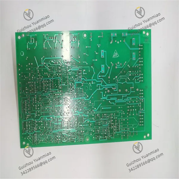
DS2020FEXAG4 (1)


4. Common Faults and Troubleshooting Methods


Fault 1: Abnormal Output Voltage

  • Symptom: The output voltage of one or more channels of DS2020PDMAG6 exceeds the normal range. There may be situations such as excessively high voltage, excessively low voltage, or large voltage fluctuations, causing the connected equipment to fail to work normally and possibly even damaging the equipment.
  • Possible Causes:
    • Abnormal input voltage (e.g., excessively high, excessively low, or unstable), which affects the normal conversion and output of the module;

    • Faults in the voltage regulation circuit inside the module (e.g., damaged regulation chip, changed parameters of resistors and capacitors), leading to uncontrollable output voltage;

    • Short circuit or overload of the output load, which affects the output voltage;

    • Long-term operation of the module, resulting in aging of some components and decreased performance, which affects the stability of voltage output.

  • Troubleshooting Methods:
  1. First, use tools such as a multimeter to measure the input voltage and confirm whether the input voltage is within the normal range (220V AC ±10%). If the input voltage is abnormal, troubleshoot the front-end power supply system, such as checking transformers, voltage regulators, and other equipment.

  2. If the input voltage is normal, inspect the voltage regulation circuit inside the module. By comparing the circuit parameters of a normal module and using instruments such as an oscilloscope to measure the voltage waveform at key nodes, determine whether components such as the regulation chip, resistors, and capacitors are damaged. Replace the corresponding components if any damage is found.

  3. Then, check the output load. Measure the output voltage after disconnecting the load. If the voltage returns to normal, it indicates a problem with the load. Troubleshoot the causes of load short circuit or overload, and repair or replace the load equipment.

  4. For problems caused by component aging, preventive replacement of easily aging components (such as capacitors) can be carried out according to the actual situation, and a comprehensive performance test of the module can be conducted to ensure that the output voltage returns to normal.


Fault 2: Communication Fault

  • Symptom: DS2020PDMAG6 cannot establish a communication connection with the upper-level computer monitoring system, or problems such as data loss, errors, and interruptions occur during communication. This prevents operation and maintenance personnel from obtaining the module's operating information in real time and from remotely controlling it.
  • Possible Causes:
    • Damaged or loose communication cables, resulting in interruption of the physical connection;

    • Faults in the communication interface module (e.g., damaged interface chip, short circuit or open circuit of the interface circuit);

    • Incorrect configuration of communication parameters (including baud rate, data bits, stop bits, parity bits, etc.) that do not match those of the upper-level computer;

    • Abnormal communication control program inside the module, which fails to process communication data normally.

  • Troubleshooting Methods:
  1. Carefully inspect the communication cables, check for damage, breakage, aging, and other phenomena, and re-plug the interfaces at both ends of the cables to ensure a secure connection.

  2. If the cables are in good condition, use professional testing tools to inspect the communication interface module, measure the electrical parameters of the interface circuit, and determine whether components such as the interface chip are damaged. Replace the communication interface module if any damage is found.

  3. Verify the communication parameters to ensure they are consistent with the settings of the upper-level computer monitoring system. Reconfigure the parameters if necessary and conduct communication tests.

  4. If it is suspected that the problem is caused by an abnormal communication control program inside the module, try resetting the module. If the problem persists, contact GE professional technicians to obtain the corresponding software upgrade package or repair program, and update the module's software to restore normal communication functions.


Fault 3: Frequent Triggering of Overcurrent Protection

  • Symptom: DS2020PDMAG6 frequently triggers overcurrent protection, resulting in output interruption and intermittent power failure of the connected equipment. This affects the normal operation of the equipment and may cause frequent startup and shutdown of the equipment, shortening its service life.
  • Possible Causes:
    • The actual current of the output load exceeds the rated current of the corresponding output channel of the module. This may be due to faults in the load equipment (e.g., short circuit of the motor winding, short circuit of the internal circuit of the equipment), leading to excessive current;

    • Faults in the current detection circuit inside the module, which misjudges the current magnitude, resulting in false triggering of overcurrent protection;

    • Poor contact in the connecting lines, which generates additional heat at locations with large contact resistance, increasing the equivalent resistance of the lines and causing the current to rise, thereby triggering overcurrent protection.

  • Troubleshooting Methods:
  1. First, use tools such as a clamp ammeter to measure the actual current of the output load and compare it with the rated current of the corresponding output channel of the module. If the load current is excessive, troubleshoot the load equipment, such as conducting an insulation test on the motor and checking for short circuits in the internal circuit of the equipment, and repair or replace the faulty load equipment.

  2. If the load current is normal, inspect the current detection circuit inside the module. Use precision instruments to measure the parameters of current detection components (such as current transformers, sampling resistors, etc.) and determine whether there is component damage or parameter drift. Replace the relevant components if any problems are found.

  3. At the same time, carefully inspect the connecting lines, check for loose or oxidized connectors, clean and fasten the poorly contacted parts to ensure reliable connection, eliminate current anomalies caused by line problems, and solve the problem of frequent triggering of overcurrent protection.


Fault 4: Module Overheating

  • Symptom: DS2020PDMAG6 has an excessively high temperature during operation, with the module surface temperature exceeding the normal operating temperature range (0℃ - 50℃). This may be accompanied by phenomena such as accelerated speed of the cooling fan and abnormal noise. In severe cases, it may cause the module to automatically operate at reduced capacity or shut down due to faults.
  • Possible Causes:
    • Poor ventilation in the module installation environment and insufficient heat dissipation space, resulting in ineffective heat dissipation;

    • The module operates under high load for a long time, with large power consumption and excessive heat generation;

    • Poor contact between the heat sink inside the module and the heat-generating components, affecting the heat transfer to the heat sink;

    • Faults in the cooling fan (e.g., damaged fan blades, stuck motor), which fails to operate normally for heat dissipation.

  • Troubleshooting Methods:
  1. Improve the module's installation environment, ensure that the control cabinet has sufficient vents and good air circulation, add cooling fans or optimize the air duct design to provide sufficient heat dissipation space for the module.

  2. Reasonably plan the module's load to avoid long-term high-load operation. The module's workload can be reduced by optimizing the system configuration and adjusting the equipment operating parameters.

  3. Open the module housing, check whether the thermal grease between the heat sink and the heat-generating components (such as power chips) is dry and whether the heat sink is securely installed. If there are problems, reapply the thermal grease and fasten the heat sink to ensure good heat transfer.

  4. Inspect the cooling fan, clean the dust and debris on the fan blades, and replace the cooling fan with a new one if the fan motor is damaged to restore the module's normal heat dissipation function and control the temperature within a reasonable range.

Product Tags: DS2020PDMAG6

Send Inquiry to This Supplier

* Message
0/5000

Want the best price? Post an RFQ now!
Verified Business License
Business Type
Trading Company
Year Established
2014
Factory Size
1,000-3,000 square meters
Product Certifications
SA8000


