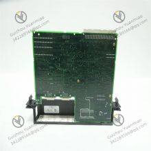
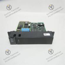
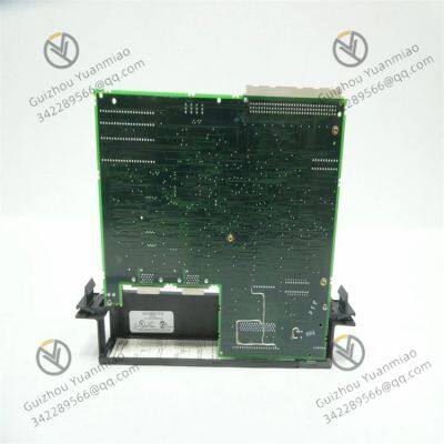
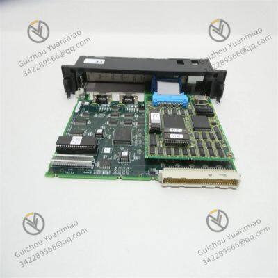
GE IC697BEM721 90-70 Series I/O Link Interface Module

The IC697BEM721 is an important I/O link interface module in the GE Fanuc 90-70 series PLCs. It is specifically designed to enable high-speed serial communication between the main controller and distributed I/O systems, and serves as a key component in building large-scale industrial automation networks. The following is a detailed explanation from the aspects of functional positioning, technical parameters, characteristics, and application scenarios:
I. Core Functional Positioning
As an I/O link interface of the 90-70 series, the core function of the IC697BEM721 is to connect the CPU of the main rack with remote I/O modules and subsystems (such as distributed digital/analog modules and intelligent sensors) through serial communication links (such as GE's proprietary Genius bus or other industrial serial protocols). It addresses the communication needs of decentralized I/O devices and expands the control range of the system.

II. Key Technical Parameters and Characteristics1. Communication Specifications
Interface Type: Dual 20-pin RS-422/485 serial ports (with differential signal transmission), supporting half-duplex/full-duplex modes, suitable for long-distance communication in industrial fields.
Communication Protocol: Compatible with GE's proprietary I/O link protocols (such as Genius I/O bus) or supports standard serial protocols (specifics need to refer to the configuration), ensuring seamless communication with 90-70 series CPUs and remote I/O modules.
Transmission Rate: Usually supports multiple selectable rates (e.g., 1200 bps to 1 Mbps), which can be adjusted according to communication distance and real-time requirements (the longer the distance, the rate can be appropriately reduced).
Maximum Communication Distance: A single segment of the line can reach 1200 meters (can be further extended with repeaters), meeting the connection requirements of scattered equipment at the workshop and factory levels.
2. I/O Expansion Capability
Supports remote expansion of up to 1024 discrete I/O points or 64 analog I/O channels, covering the needs of small and medium-sized distributed control systems.
Can connect multiple remote I/O stations (e.g., expanded via splitters) to realize multi-node data aggregation and issuance of control commands.
3. Real-time Performance and Synchronization
Adopts a priority communication mechanism to ensure the priority transmission of key I/O data (such as emergency stop signals and fault alarms), with delays controllable at the millisecond level, meeting the real-time requirements of industrial control.
Supports clock synchronization between remote I/O modules and the main rack, ensuring the consistency of actions of distributed devices (such as timing matching of output signals from multiple stations).
4. Fault Diagnosis and Reliability
Self-diagnostic Function: Can monitor the status of the communication link (such as disconnection, signal attenuation, and parity errors), and intuitively display fault types through module indicator lights (such as COM lights and FAULT lights).
Alarm Mechanism: Fault information can be fed back to the main rack CPU through the bus, triggering system alarms (such as HMI displays and sound-light alarms), facilitating quick location of problem nodes.
Anti-interference Design: Equipped with an electromagnetic shielding shell and differential signal transmission, it resists electromagnetic interference in industrial sites (such as high-frequency noise from motors and frequency converters) to ensure communication stability.
5. Electrical and Installation Characteristics
Operating Voltage: 5V DC (powered by the rack backplane), power consumption of approximately 5W, backplane current consumption of 1.3A, compatible with 90-70 series rack power supplies.
Mechanical Design: Adopts a keyed slot design to prevent incorrect insertion; the module size is adapted to 90-70 series standard racks (e.g., approximately 140mm × 60mm × 25mm, subject to the actual product).
Installation Method: Supports DIN rail mounting, facilitating integration with other modules into control cabinets; hot swapping is supported in some scenarios (model confirmation is required) for convenient online maintenance.
Environmental Adaptability: Operating temperature ranges from -20°C to 60°C, and storage temperature ranges from -40°C to 85°C, adapting to industrial-grade wide-temperature environments; shock-resistant (30g) and vibration-resistant (5-2kHz) designs adapt to the mechanical environment of workshop equipment operation.

III. Differences from Modules in the Same Series
The core differences between the IC697BEM721 and the IC697BEM713/711 (bus expansion modules) are as follows:
Expansion Method: The BEM721 focuses on serial link expansion (connecting remote I/O devices), while the BEM713/711 is for VME bus expansion (extending the main rack bus to local expansion racks).
Application Scenarios: The BEM721 is suitable for scenarios where I/O devices are physically scattered (such as across workshops), while the BEM713/711 is suitable for the expansion of multiple racks within the same control cabinet.
IV. Typical Application Scenarios
Distributed Production Lines: Such as automobile parts assembly lines, where sensors and actuators scattered at different stations are connected to the main controller through the BEM721 to achieve centralized monitoring and control.
CNC Machine Tool Networking: Connects I/O signals of multiple CNC machine tools (such as spindle status and feed axis position), and coordinates equipment linkage through the main PLC.
Smart Workshop Transformation: In the upgrading of old production lines, new remote sensors/actuators are connected through the BEM721, avoiding rewiring and reducing transformation costs.
V. Summary
The IC697BEM721 is a core interface module for realizing distributed I/O control in 90-70 series PLCs. It expands the I/O range of the system through serial communication links, and balances real-time performance, reliability, and anti-interference ability, making it suitable for centralized management of scattered devices in small and medium-sized industrial automation scenarios. In practical applications, configuration and debugging should be carried out with reference to the GE official manual, considering system scale, communication distance, and protocol compatibility.