Home > Electrical & Electronics > Electrical Control System > GE IC695PMM335 Pulse Measurement and Motion Control Module

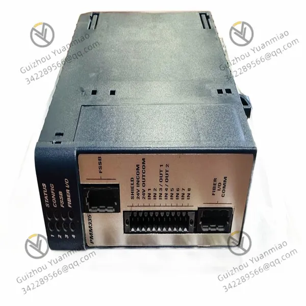
GE IC695PMM335 Pulse Measurement and Motion Control Module
GE IC695PMM335 Pulse Measurement and Motion Control Module photo-1
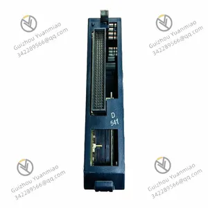
GE IC695PMM335 Pulse Measurement and Motion Control Module photo-2
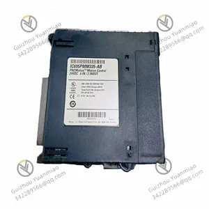
GE IC695PMM335 Pulse Measurement and Motion Control Module photo-3
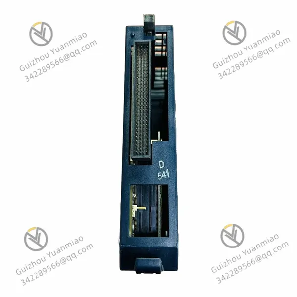
Negotiable MOQ: 1 Piece (Price negotiable depending on order volume and customization)
Key Specifications
Get Latest Price
Material:
Other
Certification:
Other
Function:
Other
Payment & Shipping
Payment Methods:
Port of Shipment:
China
Delivery Detail:
Delivery time depends on order quantity.
Material Other
Certification Other
Function Other
Condition Other
Task Other
Mathematical Model Other
Signal Other
Customized Other
Structure Other
GE  IC695PMM335  Pulse Measurement and Motion Control Module
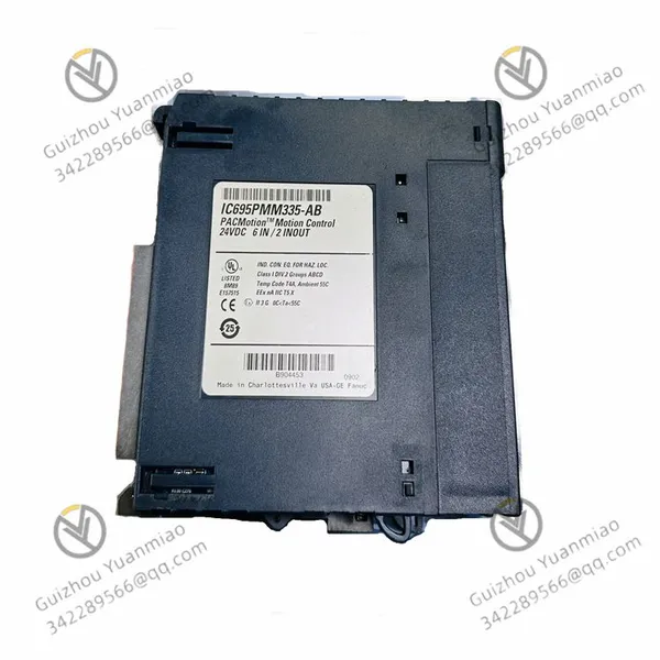

I. Module Positioning and Functional Overview
The IC695PMM335 is a pulse measurement and motion control module in GE PACSystems RX3i series, primarily used for high-precision measurement, counting of pulse signals, and simple motion control in industrial automation scenarios. Its core functions include:


  • Collecting external pulse signals (e.g., encoders, proximity switches) and converting them into physical quantities such as position and speed;

  • Achieving closed-loop control based on pulse data (e.g., positioning control of servo motors, stepper motors);

  • Supporting data interaction with the CPU of the RX3i system to enable complex logic operations and system integration.

IC695PMM335—01
II. Hardware Architecture and Key Components
The working principle of IC695PMM335 relies on its hardware design, with main components and functions as follows:
1. Signal Input Interface
  • Interface Type: Typically differential or open-collector (OC) input, supporting high-speed pulse signals (maximum frequency up to tens of kHz).

  • Input Channels: Generally includes 4 independent input channels, enabling simultaneous connection of multiple encoder or sensor signals.

  • Signal Processing: Eliminates noise through hardware filtering and shaping circuits to ensure the accuracy of pulse signals.

2. Pulse Counting and Measurement Unit
  • Counter Type: Each channel is equipped with an independent 32-bit or 64-bit hardware counter, supporting:

    • Incremental counting (forward/reverse pulse accumulation, such as encoder rotation counting);

    • Absolute counting (positioning based on reference points);

    • Frequency measurement (number of pulses per unit time for speed calculation).

  • Trigger Mechanism: Supports external triggering (e.g., limit switches) or software triggering to capture pulse events in real time.

3. Motion Control Logic Unit
  • Control Modes:

    • Position control: Controls motor displacement based on preset pulse counts (e.g., point-to-point motion);

    • Speed control: Regulates motor speed by adjusting pulse frequency;

    • Torque control (in some scenarios): Achieves torque closed-loop with external feedback.

  • Interpolation and Smoothing Algorithms: Mathematically processes pulse data to avoid jitter or overshoot during motion.

4. Communication and Data Processing Module
  • Internal Communication: Real-time data exchange with the CPU via the RX3i backplane bus (e.g., current position, fault status).

  • Protocol Support: Supports industrial bus protocols such as Profibus and EtherNet/IP (requires collaboration with other modules) to enable communication with master stations or third-party devices.

  • Data Caching: Built-in FIFO (First-In-First-Out) buffer temporarily stores high-frequency pulse data to prevent loss.

5. Status Indication and Diagnostic Unit
  • LED Indicators: Displays power, communication, counting status, and fault information (e.g., overflow, signal loss).

  • Diagnostic Functions: Monitors hardware anomalies (e.g., overload, overheating) in real time and sends alarm signals to the CPU.


III. Analysis of Core Workflow
The working principle of IC695PMM335 can be divided into four stages: signal collection, data processing, control output, and system interaction:
1. Pulse Signal Collection and Counting
  • Signal Input: Pulse signals generated by external devices (e.g., encoders) enter the module through the input interface.

  • Hardware Counting: The counter accumulates pulses in real time and determines forward/reverse motion based on signal direction (A/B phase quadrature pulses).

  • Example: When the encoder rotates with the motor, the phase difference (90°) between A and B phase pulses is used to determine the rotation direction, and the number of pulses corresponds to the rotation angle.

2. Data Processing and Physical Quantity Conversion
  • Counting Data Analysis: The module converts pulse counts into actual physical quantities (e.g., position, speed) using the following formulas:

    • Position (mm) = Pulse count × Encoder resolution × Mechanical transmission ratio

    • Speed (mm/s) = Pulse count per unit time × Resolution × Transmission ratio

  • Filtering and Calibration: Eliminates signal jitter through software algorithms (e.g., moving average filtering) to ensure data stability.

3. Execution of Motion Control Logic
  • Closed-loop Control Flow:

  1. Receives target position/speed parameters from the CPU or master station;

  2. Calculates the deviation between the current actual value and the target value;

  3. Adjusts output via PWM (Pulse Width Modulation) or pulse frequency to control the motor driver;

  4. Collects encoder feedback in real time to adjust control parameters until the target value is reached.

  • Typical Scenario: In machine tool feed shaft control, the module outputs corresponding pulse sequences to drive the servo motor based on the target position sent by the PLC, while ensuring positioning accuracy through encoder feedback.

  • 4. Interaction with RX3i System
    • Data Interaction: The module transmits real-time data (e.g., current position, operating status) to the CPU via the backplane bus, while receiving control instructions from the CPU (e.g., start/stop motion, modify parameters).

    • Programming Interface: Configures module parameters (e.g., counting mode, pulse equivalent) and writes control logic (e.g., motion trajectory planning) through GE's Machine Edition software.

    IC695PMM335—02
    IV. Key Technical Features and Advantages
    • High-speed Counting Capability: Supports pulse frequencies up to tens of kHz, suitable for high-speed motion scenarios (e.g., packaging machinery, electronic processing equipment).

    • High-precision Positioning: Positioning errors can be controlled within the micrometer level through hardware counters and interpolation algorithms.

    • Flexible Trigger Mechanism: Supports hardware triggering (e.g., limit switches) and software triggering to meet dynamic response requirements (e.g., emergency stop, zero point calibration).

    • Multi-channel Synchronous Control: 4 independent channels can simultaneously handle motion control of multiple axes to achieve multi-axis collaboration (e.g., Cartesian robots).

    V. Typical Application ScenariosManufacturing Automation
    • Axial positioning control of CNC machine tools (X/Y/Z axis feeding);

    • Precision displacement control of electronic component placement machines.

    Logistics and Warehousing
    • Horizontal/vertical motion positioning of stacker cranes in automated stereo warehouses;

    • Synchronous speed control of conveyor lines.

    Packaging Machinery
    • Fixed-length cutting and position control for sealing machines and filling machines;

    • Ribbon feeding synchronization for label printers.

    VI. Collaborative Work with Other Modules
    • Collaboration with CPU Module: Achieves programming and scheduling of motion logic through the RX3i CPU, such as multi-axis interpolation motion (linear/circular interpolation).

    • Collaboration with Communication Modules: Accesses the master station network via Profibus or Ethernet modules to enable remote monitoring and parameter adjustment (e.g., issuing motion commands from the SCADA system).

    • Collaboration with I/O Modules: Processes external inputs such as limit switches and origin signals in conjunction with digital I/O modules to implement safety protection logic.

    VII. Conclusion

    The working principle of the IC695PMM335 module essentially combines hardware pulse counting with software logic control to convert motion signals from the physical world into calculable and controllable data, and then achieves precise motion control through industrial automation systems. Its core advantages lie in high-speed response, high-precision measurement, and deep integration with the RX3i system, making it suitable for industrial scenarios requiring precise position and speed control.


    IC695PMM335—03


    Product Tags: IC695PMM335

    Send Inquiry to This Supplier

    * Message
    0/5000

    Want the best price? Post an RFQ now!
    Verified Business License
    Business Type
    Trading Company
    Year Established
    2014
    Factory Size
    1,000-3,000 square meters
    Product Certifications
    SA8000